

Fiber Optic Design Guide - Maite y Mario
Fiber Optic Design Guide - Maite y Mario
Fiber Optic Design Guide - Maite y Mario

Create successful ePaper yourself
Turn your PDF publications into a flip-book with our unique Google optimized e-Paper software.
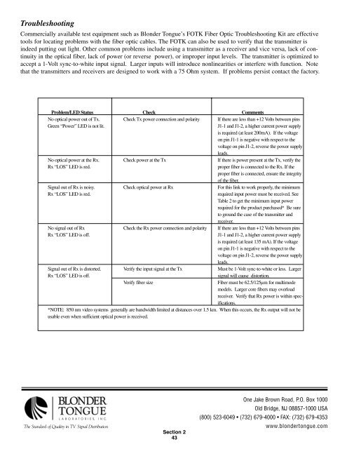
Troubleshooting<br />
Commercially available test equipment such as Blonder Tongue’s FOTK <strong>Fiber</strong> <strong>Optic</strong> Troubleshooting Kit are effective<br />
tools for locating problems with the fiber optic cables. The FOTK can also be used to verify that the transmitter is<br />
indeed putting out light. Other common problems include using a transmitter as a receiver and vice versa, lack of continuity<br />
in the optical fiber, lack of power (or reverse power), or improper input levels. The transmitter is optimized to<br />
accept a 1-Volt sync-to-white input signal. Larger inputs will introduce nonlinearities or interfere with function. Note<br />
that the transmitters and receivers are designed to work with a 75 Ohm system. If problems persist contact the factory.<br />
Problem/LED Status Check Comments<br />
No optical power out of Tx. Check Tx power connection and polarity If there are less than +12 Volts between pins<br />
Green “Power” LED is not lit. J1-1 and J1-2, a higher current power supply<br />
is required (at least 200mA). If the voltage<br />
on pin J1-1 is negative with respect to the<br />
voltage on pin J1-2, reverse the power supply<br />
leads.<br />
No optical power at the Rx. Check power at the Tx If there is power present at the Tx, verify the<br />
Rx “LOS” LED is red. proper fiber is connected to the Rx. If the<br />
proper fiber is connected, ensure the integrity<br />
of the fiber.<br />
Signal out of Rx is noisy. Check optical power at Rx For this link to work properly, the minimum<br />
Rx “LOS” LED is red. required input power must be received. See<br />
Table 2 to get the minimum input power<br />
required for the product purchased* Be sure<br />
to ground the case of the transmitter and<br />
receiver.<br />
No signal out of Rx Check the Rx power connection and polarity If there are less than +12 Volts between pins<br />
Rx “LOS” LED is off. J1-1 and J1-2, a higher current power supply<br />
is required (at least 135 mA). If the voltage<br />
on pin J1-1 is negative with respect to the<br />
voltage on pin J1-2, reverse the power supply<br />
leads.<br />
Signal out of Rx is distorted. Verify the input signal at the Tx Must be 1-Volt sync-to-white or less. Larger<br />
Rx “LOS” LED is off. signal will cause distortion.<br />
Verify fiber size <strong>Fiber</strong> must be 62.5/125µm for multimode<br />
models. Larger core fibers may overload<br />
receiver. Verify that Rx power is within specifications.<br />
*NOTE: 850 nm video systems generally are bandwidth limited at distances over 1.5 km. When this occurs, the Rx output will not be<br />
usable even when sufficient optical power is received.<br />
LABORATORIES, INC.<br />
The Standard of Quality in TV Signal Distribution<br />
Section 2<br />
43<br />
One Jake Brown Road, P.O. Box 1000<br />
Old Bridge, NJ 08857-1000 USA<br />
(800) 523-6049 • (732) 679-4000 • FAX: (732) 679-4353<br />
www.blondertongue.com