

Fiber Optic Design Guide - Maite y Mario
Fiber Optic Design Guide - Maite y Mario
Fiber Optic Design Guide - Maite y Mario

You also want an ePaper? Increase the reach of your titles
YUMPU automatically turns print PDFs into web optimized ePapers that Google loves.
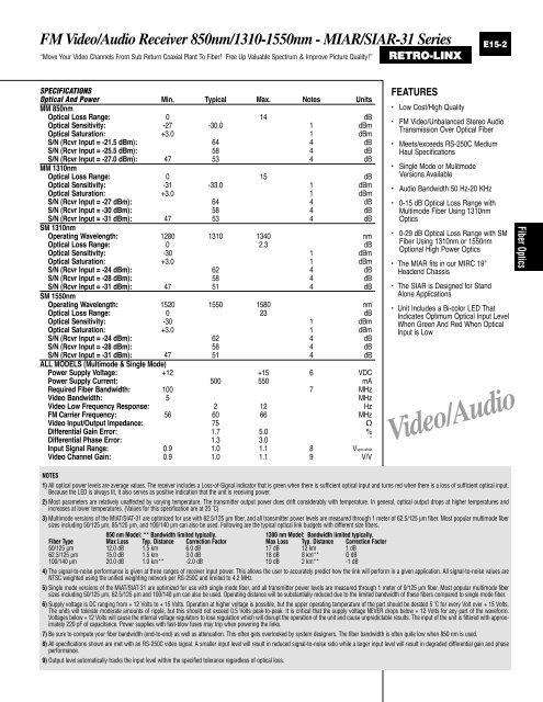
FM Video/Audio Receiver 850nm/1310-1550nm - MIAR/SIAR-31 Series<br />
“Move Your Video Channels From Sub Return Coaxial Plant To <strong>Fiber</strong>! Free Up Valuable Spectrum & Improve Picture Quality!” RETRO-LINX<br />
SPECIFICATIONS<br />
<strong>Optic</strong>al And Power Min. Typical Max. Notes Units<br />
MM 850nm<br />
<strong>Optic</strong>al Loss Range: 0 14 dB<br />
<strong>Optic</strong>al Sensitivity: -27 -30.0 1 dBm<br />
<strong>Optic</strong>al Saturation: +3.0 1 dBm<br />
S/N (Rcvr Input = -21.5 dBm): 64 4 dB<br />
S/N (Rcvr Input = -25.5 dBm): 58 4 dB<br />
S/N (Rcvr Input = -27.0 dBm): 47 53 4 dB<br />
MM 1310nm<br />
<strong>Optic</strong>al Loss Range: 0 15 dB<br />
<strong>Optic</strong>al Sensitivity: -31 -33.0 1 dBm<br />
<strong>Optic</strong>al Saturation: +3.0 1 dBm<br />
S/N (Rcvr Input = -27 dBm): 64 4 dB<br />
S/N (Rcvr Input = -30 dBm): 58 4 dB<br />
S/N (Rcvr Input = -31 dBm): 47 53 4 dB<br />
SM 1310nm<br />
Operating Wavelength: 1280 1310 1340 nm<br />
<strong>Optic</strong>al Loss Range: 0 2.3 dB<br />
<strong>Optic</strong>al Sensitivity: -30 1 dBm<br />
<strong>Optic</strong>al Saturation: +3.0 1 dBm<br />
S/N (Rcvr Input = -24 dBm): 62 4 dB<br />
S/N (Rcvr Input = -28 dBm): 58 4 dB<br />
S/N (Rcvr Input = -31 dBm): 47 51 4 dB<br />
SM 1550nm<br />
Operating Wavelength: 1520 1550 1580 nm<br />
<strong>Optic</strong>al Loss Range: 0 23 dB<br />
<strong>Optic</strong>al Sensitivity: -30 1 dBm<br />
<strong>Optic</strong>al Saturation: +3.0 1 dBm<br />
S/N (Rcvr Input = -24 dBm): 62 4 dB<br />
S/N (Rcvr Input = -28 dBm): 58 4 dB<br />
S/N (Rcvr Input = -31 dBm): 47 51 4 dB<br />
ALL MODELS (Multimode & Single Mode)<br />
Power Supply Voltage: +12 +15 6 VDC<br />
Power Supply Current: 500 550 mA<br />
Required <strong>Fiber</strong> Bandwidth: 100 7 MHz<br />
Video Bandwidth: 5 MHz<br />
Video Low Frequency Response: 2 12 Hz<br />
FM Carrier Frequency: 56 60 66 MHz<br />
Video Input/Output Impedance: 75 Ω<br />
Differential Gain Error: 1.7 5.0 %<br />
Differential Phase Error: 1.3 3.0 ˚<br />
Input Signal Range: 0.9 1.0 1.1 8 Vsync-white<br />
Video Channel Gain: 0.9 1.0 1.1 9 V/V<br />
FEATURES<br />
E15-2<br />
Low Cost/High Quality<br />
FM Video/Unbalanced Stereo Audio<br />
Transmission Over <strong>Optic</strong>al <strong>Fiber</strong><br />
Meets/exceeds RS-250C Medium<br />
Haul Specifications<br />
Single Mode or Mulitmode<br />
Versions Available<br />
Audio Bandwidth 50 Hz-20 KHz<br />
0-15 dB <strong>Optic</strong>al Loss Range with<br />
Multimode <strong>Fiber</strong> Using 1310nm<br />
<strong>Optic</strong>s<br />
0-29 dB <strong>Optic</strong>al Loss Range with SM<br />
<strong>Fiber</strong> Using 1310nm or 1550nm<br />
Optional High Power <strong>Optic</strong>s<br />
The MIAR fits in our MIRC 19”<br />
Headend Chassis<br />
The SIAR is <strong>Design</strong>ed for Stand<br />
Alone Applications<br />
Unit Includes a Bi-color LED That<br />
Indicates Optimum <strong>Optic</strong>al Input Level<br />
When Green And Red When <strong>Optic</strong>al<br />
Input is Low<br />
Video/Audio<br />
NOTES<br />
1) All optical power levels are average values. The receiver includes a Loss-of-Signal indicator that is green when there is sufficient optical input and turns red when there is a loss of sufficient optical input.<br />
Because the LED is always lit, it also serves as positive indication that the unit is receiving power.<br />
2) Most parameters are relatively unaffected by varying temperature. The transmitter output power does drift considerably with temperature. In general, optical output drops at higher temperatures and<br />
increases at lower temperatures. (Values for this specification are at 25 ˚C)<br />
3) Multimode versions of the MIAT/SIAT-31 are optimized for use with 62.5/125 µm fiber, and all transmitter power levels are measured through 1 meter of 62.5/125 µm fiber. Most popular multimode fiber<br />
sizes including 50/125 µm, 85/125 µm, and 100/140 µm can also be used. Following are the typical optical link budgets with different size fibers.<br />
850 nm Model: ** Bandwidth limited typically. 1300 nm Model: Bandwidth limited typically.<br />
<strong>Fiber</strong> Type Max Loss Typ. Distance Correction Factor Max Loss Typ. Distance Correction Factor<br />
50/125 µm 12.0 dB 1.5 km 6.0 dB 17 dB 12 km 1 dB<br />
62.5/125 µm 15.0 dB 1.5 km 3.0 dB 18 dB 8 km** O dB<br />
100/140 µm 20.0 dB 1.0 km** -2.0 dB 19 dB 2 km** -1 dB<br />
4) The signal-to-noise performance is given at three ranges of receiver input power. This allows the user to accurately predict how the link will perform in a given application. All signal-to-noise values are<br />
NTSC weighted using the unified weighting network per RS-250C and limited to 4.2 MHz.<br />
5) Single mode versions of the MIAT/SIAT-31 are optimized for use with single mode fiber, and all transmitter power levels are measured through 1 meter of 9/125 µm fiber. Most popular multimode fiber<br />
sizes including 50/125 µm, 62.5/125 µm and 100/140 µm can also be used. Operating distance will be substantially reduced due to the limited bandwidth of these fibers compared to single mode fiber.<br />
6) Supply voltage is DC ranging from + 12 Volts to + 15 Volts. Operation at higher voltage is possible, but the upper operating temperature of the part should be derated 5 ˚C for every Volt over + 15 Volts.<br />
The units will tolerate moderate amounts of ripple, but this should not exceed 0.5 Volts peak-to-peak. It is critical that the supply voltage NEVER drops below + 12 Volts for any part of the waveform.<br />
Voltages below + 12 Volts will cause the internal voltage regulators to lose regulation which will disrupt the operation of the unit and cause unpredictable results. The input of the unit is filtered with approximately<br />
220 pF of capacitance. Power supplies with fast-blow fuses may trip when powering the links.<br />
7) Be sure to compute your fiber bandwidth (end-to-end) as well as attenuation. This often gets overlooked by system designers. The fiber bandwidth is often quite low when 850 nm is used.<br />
8) All specifications shown are met with an RS-250C video signal. A smaller input level will result in reduced signal-to-noise ratio while a larger input level will result in degraded differential gain and phase<br />
performance.<br />
9) Output level automatically tracks the input level within the specified tolerance regardless of optical loss.<br />
<strong>Fiber</strong> <strong>Optic</strong>s