

Fiber Optic Design Guide - Maite y Mario
Fiber Optic Design Guide - Maite y Mario
Fiber Optic Design Guide - Maite y Mario

Create successful ePaper yourself
Turn your PDF publications into a flip-book with our unique Google optimized e-Paper software.
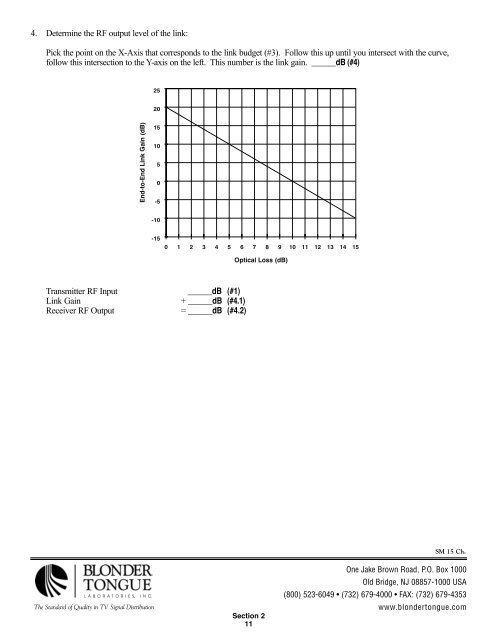
4. Determine the RF output level of the link:<br />
Pick the point on the X-Axis that corresponds to the link budget (#3). Follow this up until you intersect with the curve,<br />
follow this intersection to the Y-axis on the left. This number is the link gain. ______dB (#4)<br />
Transmitter RF Input ______dB (#1)<br />
Link Gain + ______dB (#4.1)<br />
Receiver RF Output = ______dB (#4.2)<br />
LABORATORIES, INC.<br />
The Standard of Quality in TV Signal Distribution<br />
Section 2<br />
11<br />
SM 15 Ch.<br />
One Jake Brown Road, P.O. Box 1000<br />
Old Bridge, NJ 08857-1000 USA<br />
(800) 523-6049 • (732) 679-4000 • FAX: (732) 679-4353<br />
www.blondertongue.com