

Fiber Optic Design Guide - Maite y Mario
Fiber Optic Design Guide - Maite y Mario
Fiber Optic Design Guide - Maite y Mario

You also want an ePaper? Increase the reach of your titles
YUMPU automatically turns print PDFs into web optimized ePapers that Google loves.
Connections<br />
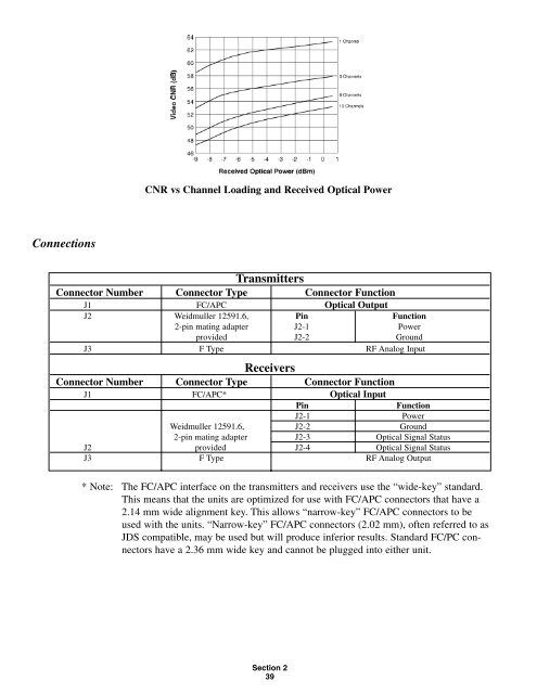
CNR vs Channel Loading and Received <strong>Optic</strong>al Power<br />
Transmitters<br />
Connector Number Connector Type Connector Function<br />
J1 FC/APC <strong>Optic</strong>al Output<br />
J2 Weidmuller 12591.6, Pin Function<br />
2-pin mating adapter J2-1 Power<br />
provided J2-2 Ground<br />
J3 F Type RF Analog Input<br />
Receivers<br />
Connector Number Connector Type Connector Function<br />
J1 FC/APC* <strong>Optic</strong>al Input<br />
Pin Function<br />
J2-1 Power<br />
Weidmuller 12591.6, J2-2 Ground<br />
2-pin mating adapter J2-3 <strong>Optic</strong>al Signal Status<br />
J2 provided J2-4 <strong>Optic</strong>al Signal Status<br />
J3 F Type RF Analog Output<br />
* Note: The FC/APC interface on the transmitters and receivers use the “wide-key” standard.<br />
This means that the units are optimized for use with FC/APC connectors that have a<br />
2.14 mm wide alignment key. This allows “narrow-key” FC/APC connectors to be<br />
used with the units. “Narrow-key” FC/APC connectors (2.02 mm), often referred to as<br />
JDS compatible, may be used but will produce inferior results. Standard FC/PC connectors<br />
have a 2.36 mm wide key and cannot be plugged into either unit.<br />
Section 2<br />
39