

Fiber Optic Design Guide - Maite y Mario
Fiber Optic Design Guide - Maite y Mario
Fiber Optic Design Guide - Maite y Mario

Create successful ePaper yourself
Turn your PDF publications into a flip-book with our unique Google optimized e-Paper software.
<strong>Fiber</strong> <strong>Optic</strong>s<br />
E2-3<br />
Example<br />
<strong>Fiber</strong> <strong>Optic</strong><br />
FIBT <strong>Design</strong> Tool<br />
#1. The C/N you would<br />
like to see from the<br />
link is 54 dB.<br />
#2. The system has 78<br />
channels. The C/N<br />
of 54 dB intersects<br />
with the 78 channel<br />
curve at 3 dBm.<br />
#3. The optical link<br />
budget for this link<br />
is 7 dBm.<br />
#4. Link<br />
Budget: 7 dBm<br />
Receiver<br />
Input: +3 dBm<br />
Minimum<br />
Tx<br />
Output: 10 dBm<br />
Round up to 11 dBm<br />
☞ Please Order by Stock Number!<br />
www.blondertongue.com<br />
Toll Free For Ordering!<br />
800-523-6049<br />
FAX 800-336-6295<br />
1. What is the acceptable C/N you want to see at the output of the fiber optic receiver?<br />
__________dB (#1)<br />
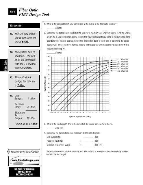
2. Determine the optical input needed at the receiver to maintain your C/N from above. Find the C/N fig-<br />
Carrier-to-Noise (dB)<br />
ure on the Y axis on the chart below. Follow that figure across until you come to the curve that corre-<br />
sponds to your channel loading. Follow this intersection down to the X axis to determine the optical<br />
input power. This is the level that you need to hit the receiver with in order to maintain the C/N that<br />
you picked in Step #1.<br />
__________dB (#2)<br />
60<br />
58<br />
56<br />
54<br />
52<br />
50<br />
48<br />
46<br />
44<br />
42<br />
40<br />
38<br />
36<br />
-14 -13 -12 -11 -10 -9 -8 -7 -6 -5 -4 -3 -2 -1 0 1 2 3 4<br />
3. What is the link budget? This is the sum of all the losses from the Tx to the Rx.<br />
__________dBm (#3)<br />
<strong>Optic</strong>al Input Power (dBm)<br />
4. Determine the transmitter power necessary to complete the link:<br />
Link Budget (#3) ___________ dBm<br />
Receiver Input (#2) + ___________ dBm<br />
Minimum Transmitter Output = ___________ dBm (#4)<br />
5 Channels<br />
10 Channels<br />
24 Channels<br />
40 Channels<br />
78 Channels<br />
110 Channels<br />
You should round this number up to the next dBm to build in a margin of error to cover any unseen<br />
items in the link budget.