

Fiber Optic Design Guide - Maite y Mario
Fiber Optic Design Guide - Maite y Mario
Fiber Optic Design Guide - Maite y Mario

Create successful ePaper yourself
Turn your PDF publications into a flip-book with our unique Google optimized e-Paper software.
LABORATORIES, INC.<br />
The Standard of Quality in TV Signal Distribution<br />
Troubleshooting roubleshooting <strong>Guide</strong><br />
5 Channel <strong>Fiber</strong> <strong>Optic</strong> AM/VSB Video Link<br />
Transmitters<br />
Model Stock No.<br />
MIBT-M3T-25 7422<br />
SIBT-M3T-25 7422-S<br />
Receivers<br />
Model Stock No.<br />
MIBR-M3T-25 7432<br />
SIBR-M3T-25 7432-S<br />
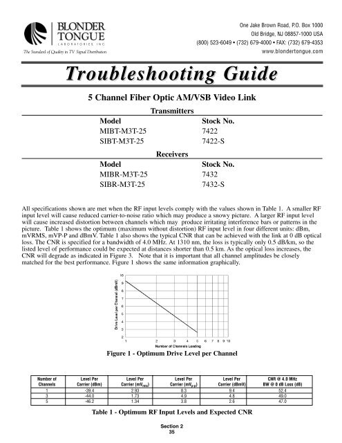
Figure 1 - Optimum Drive Level per Channel<br />
Table 1 - Optimum RF Input Levels and Expected CNR<br />
Section 2<br />
35<br />
One Jake Brown Road, P.O. Box 1000<br />
Old Bridge, NJ 08857-1000 USA<br />
(800) 523-6049 • (732) 679-4000 • FAX: (732) 679-4353<br />
www.blondertongue.com<br />
All specifications shown are met when the RF input levels comply with the values shown in Table 1. A smaller RF<br />
input level will cause reduced carrier-to-noise ratio which may produce a snowy picture. A larger RF input level<br />
will cause increased distortion between channels which may produce irritating interference bars or patterns in the<br />
picture. Table 1 shows the optimum (maximum without distortion) RF input level in four different units: dBm,<br />
mVRMS, mVP-P and dBmV. Table 1 also shows the typical CNR that can be achieved with the link at 0 dB optical<br />
loss. The CNR is specified for a bandwidth of 4.0 MHz. At 1310 nm, the loss is typically only 0.5 dB/km, so the<br />
listed level of performance could be expected at distances shorter than 0.5 km. As the optical loss increases, the<br />
CNR will degrade as indicated in Figure 3. Note that it is important that all channel amplitudes be closely<br />
matched for the best performance. Figure 1 shows the same information graphically.<br />
Number of Level Per Level Per Level Per Level Per CNR @ 4.0 MHz<br />
Channels Carrier (dBm) Carrier (mV rms) Carrier (mV p-p) Carrier (dBmV) BW @ 0 dB Loss (dB)<br />
1 -39.4 2.93 8.3 9.4 52.4<br />
3 -44.0 1.73 4.9 4.8 49.0<br />
5 -46.2 1.34 3.8 2.6 47.0