

Fiber Optic Design Guide - Maite y Mario
Fiber Optic Design Guide - Maite y Mario
Fiber Optic Design Guide - Maite y Mario

Create successful ePaper yourself
Turn your PDF publications into a flip-book with our unique Google optimized e-Paper software.
Power Meter Output (Volts)<br />
12<br />
11<br />
10<br />
9<br />
8<br />
7<br />
6<br />
5<br />
4<br />
3<br />
2<br />
1<br />
0<br />
1 2 3 4 5 6 7 8 9 10<br />
<strong>Optic</strong>al Input (mW)<br />
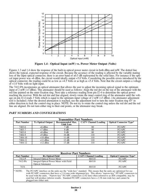
Figure 1.4 - <strong>Optic</strong>al Input (mW) vs. Power Meter Output (Volts)<br />
Figures 1.3 and 1.4 show the response of the built-in optical power meter circuit in both dBm and mW. The dotted line<br />
shows the typical, expected response of the circuit. Because the accuracy of the reading is affected by the variable mating<br />
loss of the input optical connector, there is an error band of ±0.5 dB represented by the solid lines. For instance if the optical<br />
input power was +6 dBm, the circuit would ideally output +5.0 Volts. Considering the possible errors introduced by the<br />
optical connector, the reading could be as low as +4.5 Volts or as high as +5.4 Volts. Note that the circuit outputs a voltage<br />
of +1.0 Volts with no light input.<br />
The 7412-PA incorporates an optical attenuator that allows the user to adjust the incoming optical signal to the optimum<br />
input of 2 mW (+3 dBm). This attenuator should be used as follows: Align the red dot on the top of the attenuator with the<br />
red line painted on the outer fixation ring. Next take a reference reading from pin J2-4 to determine the optical power<br />
reaching the receiver. With the red dot and line aligned, slowly rotate the inner control ring of the attenuator until the voltage<br />
on pin J2-4 reads 3 Volts which is equal to the optimum input voltage of 2 mW (+3 dBm). (An attenuator adjustment<br />
tool is included.) After the desired attenuation is reached, use the adjustment tool to turn the outer fixation ring 45° in<br />
either direction to lock the control ring in place. NOTE: Do not try to rotate the control ring unless the red dot and the red<br />
line are aligned. Do not turn either ring to their end points, or the attenuator may break.<br />
PART NUMBERS AND CONFIGURATIONS<br />
Transmitter Part Numbers<br />
Part Number Tx <strong>Optic</strong>al Output Recommended Max. CATV Channel Loading <strong>Optic</strong>al Connector Type*<br />
Link Loss<br />
7403-6 +6 dBm 7 dB 80 FC/APC<br />
7403-7 +7 dBm 8 dB 80 FC/APC<br />
7403-8 +8 dBm 9 dB 80 FC/APC<br />
7404-9 +9 dBm 10 dB 110 FC/APC<br />
7404-10 +10 dBm 11 dB 110 FC/APC<br />
7404-11 +11 dBm 12 dB 110 FC/APC<br />
7404-12 +12 dBm 13 dB 110 FC/APC<br />
Part Number Rx <strong>Optic</strong>al Field<br />
Receiver Part Numbers<br />
CATV Channel Loading <strong>Optic</strong>al Connector Type*<br />
7412-P Integral <strong>Optic</strong>al Power Meter 80/110 FC/APC<br />
7412-PA Integral <strong>Optic</strong>al Power Meter with Field<br />
<strong>Optic</strong>al Attenuator<br />
80/110 FC/APC<br />
7434 80/110 FC/APC<br />
* NOTE: The FC/APC interface on the units use the “wide-key” standard. This means that the units are optimized for use<br />
with FC/APC connectors that have a 2.14 mm wide alignment key. This allows “narrow-key” FC/APC connectors to<br />
be used with the units. “Narrow-key” FC/APC connectors (2.02 mm) often referred to as JDS compatible, may be<br />
used but will produce inferior results. Standard FC/APC connectors have a 2.36 mm wide key and cannot be<br />
plugged into either unit.<br />
Section 2<br />
28