- Page 1 and 2: Ferrari 1100 Series Service Guide S
- Page 3 and 4: Copyright Copyright © 2007 by Acer
- Page 5: Preface Before using this informati
- Page 8 and 9: Table of Contents VIII Removing the
- Page 10 and 11: Table of Contents X
- Page 12 and 13: Audio ❑ Easy-launch buttons featu
- Page 14 and 15: System Block Diagram 4 Chapter 1
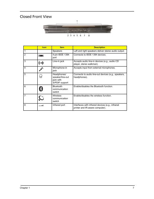
- Page 18 and 19: Left View Right View # Icon Item De
- Page 20 and 21: Bottom View 1 2 3 Icon Item Descrip
- Page 22 and 23: Press < > to run the Acer Empowerin
- Page 24 and 25: Using the Keyboard The keyboard has
- Page 26 and 27: Hot Keys The computer employs hotke
- Page 28 and 29: Acer Empowering Technology The Empo
- Page 30 and 31: Acer ePower Management Acer ePower
- Page 32 and 33: Acer eAudio Management Acer eAudio
- Page 34 and 35: The Acer eDataSecurity Management s
- Page 36 and 37: ❥User backup image ❥Current sys
- Page 38 and 39: ❑ Start Windows Mobility Center f
- Page 40 and 41: NOTE: Please ensure that the resolu
- Page 42 and 43: Hardware Specifications and Configu
- Page 44 and 45: LAN connector location Left side Fe
- Page 46 and 47: Super-Multi Drive module Loading me
- Page 48 and 49: LCD 12.1” inch Item Specification
- Page 50 and 51: Navigating the BIOS Utility There a
- Page 52 and 53: Main The Main screen allows the use
- Page 54 and 55: Advanced The Advanced screen allows
- Page 56 and 57: The table below describes the param
- Page 58 and 59: If the current password entered doe
- Page 60 and 61: Exit The Exit screen contains param
- Page 62 and 63: Remove HDD/BIOS Utility This sectio
- Page 64 and 65: ❑ If you need to solve BIOS passw
- Page 66 and 67:
56 Chapter 2
- Page 68 and 69:
General Information Pre-disassembly
- Page 70 and 71:
Removing the Battery Pack 1. Turn b
- Page 72 and 73:
2. Remove the three captive screws
- Page 74 and 75:
4. Move the antenna away from the W
- Page 76 and 77:
Main Unit Disassembly Process Main
- Page 78 and 79:
4. Remove the adhesive strip over t
- Page 80 and 81:
5. Carefully pry loose the middle c
- Page 82 and 83:
7. Carefully pull out the wireless
- Page 84 and 85:
10. Remove the four screws (A) from
- Page 86 and 87:
Step Size (Quantity) Color Torque 1
- Page 88 and 89:
13. Disconnect the fingerprint cabl
- Page 90 and 91:
Step Size (Quantity) Color Torque 1
- Page 92 and 93:
Removing theTouch Pad Board Module
- Page 94 and 95:
14. Remove the one screw (G) securi
- Page 96 and 97:
14. Disconnect the bluetooth cable
- Page 98 and 99:
Removing the CPU and VGA Heatsink M
- Page 100 and 101:
15. Lift up carefully to remove the
- Page 102 and 103:
12. See “Removing the Main Board
- Page 104 and 105:
13. Remove the one screw (E) securi
- Page 106 and 107:
Removing the LCD Bezel 1. See “Re
- Page 108 and 109:
Removing the LCD module with the Br
- Page 110 and 111:
9. Disconnect the inverter board ca
- Page 112 and 113:
10. Remove the four screws (J) secu
- Page 114 and 115:
Removing the Web Camera 1. See “R
- Page 116 and 117:
System Check Procedures External Di
- Page 118 and 119:
Check the Power Adapter Unplug the
- Page 120 and 121:
Power-On Self-Test (POST) Error Mes
- Page 122 and 123:
Error Message List Error Messages F
- Page 124 and 125:
Phoenix BIOS Beep Codes Code Beeps
- Page 126 and 127:
Code Beeps POST Routine Description
- Page 128 and 129:
Code Beeps F5h Boot to Mini DOS F6h
- Page 130 and 131:
Power-Related Symptoms Symptom / Er
- Page 132 and 133:
Keyboard/Touchpad-Related Symptoms
- Page 134 and 135:
Undetermined Problems The diagnosti
- Page 136 and 137:
Bottom View 126 Chapter 5
- Page 138 and 139:
If there is no Password request, BI
- Page 140 and 141:
130 Chapter 5
- Page 142 and 143:
Ferrari 1100 Exploded Diagram 132 C
- Page 144 and 145:
Category No. Part Name and Descript
- Page 146 and 147:
Keyboard Category No. Part Name and
- Page 148 and 149:
Miscellaneous Screws Category No. P
- Page 150 and 151:
Model Definition and Configuration
- Page 152 and 153:
Model RO Country AS505 1AWX Mi AS50
- Page 154 and 155:
Model RO Country AS505 1AWX Mi AS50
- Page 156 and 157:
Model RO Country AS505 1ANW XMi AS5
- Page 158 and 159:
Model RO Country AS505 1AWX Mi AS50
- Page 160 and 161:
Appendix A 150 AS505 1AWX Mi EMEA H
- Page 162 and 163:
Model RO Country AS505 2WXM i AS505
- Page 164 and 165:
Model RO Country AS505 1ANW XMi AS5
- Page 166 and 167:
Model RO Country AS505 1AWX Mi AS50
- Page 168 and 169:
Model RO Country AS505 1AWX Mi AS50
- Page 170 and 171:
Model RO Country AS505 1AWX Mi AS50
- Page 172 and 173:
Appendix A 162
- Page 174 and 175:
Microsoft ® Windows ® Vista Envir
- Page 176 and 177:
166 Appendix B
- Page 178 and 179:
168 Appendix C
- Page 180:
M N O P S 170 LCD Brackets 101 LCD