

Impact of Drivetrain on Wind Farm VAR Control - Upwind
Impact of Drivetrain on Wind Farm VAR Control - Upwind
Impact of Drivetrain on Wind Farm VAR Control - Upwind

Create successful ePaper yourself
Turn your PDF publications into a flip-book with our unique Google optimized e-Paper software.
UPWIND<br />
dynamic model basis as in the DFIG. Accordingly, it can be claimed that the <strong>VAR</strong> c<strong>on</strong>trol<br />
performance <str<strong>on</strong>g>of</str<strong>on</strong>g> the full c<strong>on</strong>verter WTG would be similar to that provided by the DFIG.<br />
fstator<br />
DC <strong>Wind</strong>ing<br />
fstator<br />
P stator<br />
Qstator<br />
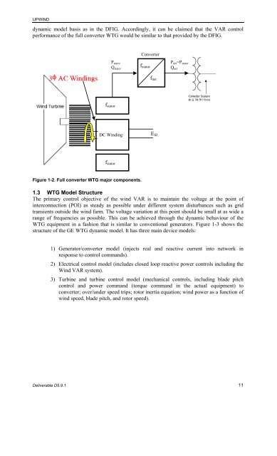
Figure 1-2. Full c<strong>on</strong>verter WTG major comp<strong>on</strong>ents.<br />
C<strong>on</strong>verter<br />
Deliverable D5.9.1 11<br />
fstator<br />
fnet<br />
Efd<br />
P net=P stator<br />
1.3 WTG Model Structure<br />
The primary c<strong>on</strong>trol objective <str<strong>on</strong>g>of</str<strong>on</strong>g> the wind <strong>VAR</strong> is to maintain the voltage at the point <str<strong>on</strong>g>of</str<strong>on</strong>g><br />
interc<strong>on</strong>necti<strong>on</strong> (POI) as steady as possible under different system disturbances such as grid<br />
transients outside the wind farm. The voltage variati<strong>on</strong> at this point should be small at as wide a<br />
range <str<strong>on</strong>g>of</str<strong>on</strong>g> frequencies as possible. This can be achieved through the dynamic behaviour <str<strong>on</strong>g>of</str<strong>on</strong>g> the<br />
WTG equipment in a fashi<strong>on</strong> that is similar to c<strong>on</strong>venti<strong>on</strong>al generators. Figure 1-3 shows the<br />
structure <str<strong>on</strong>g>of</str<strong>on</strong>g> the GE WTG dynamic model. It has three main device models:<br />
1) Generator/c<strong>on</strong>verter model (injects real and reactive current into network in<br />
resp<strong>on</strong>se to c<strong>on</strong>trol commands).<br />
2) Electrical c<strong>on</strong>trol model (includes closed loop reactive power c<strong>on</strong>trols including the<br />
<strong>Wind</strong> <strong>VAR</strong> system).<br />
3) Turbine and turbine c<strong>on</strong>trol model (mechanical c<strong>on</strong>trols, including blade pitch<br />
c<strong>on</strong>trol and power command (torque command in the actual equipment) to<br />
c<strong>on</strong>verter; over/under speed trips; rotor inertia equati<strong>on</strong>; wind power as a functi<strong>on</strong> <str<strong>on</strong>g>of</str<strong>on</strong>g><br />
wind speed, blade pitch, and rotor speed).<br />
Qnet


