

Impact of Drivetrain on Wind Farm VAR Control - Upwind
Impact of Drivetrain on Wind Farm VAR Control - Upwind
Impact of Drivetrain on Wind Farm VAR Control - Upwind

Create successful ePaper yourself
Turn your PDF publications into a flip-book with our unique Google optimized e-Paper software.
UPWIND<br />
SCR:20<br />
SCR:5<br />
SCR:3<br />
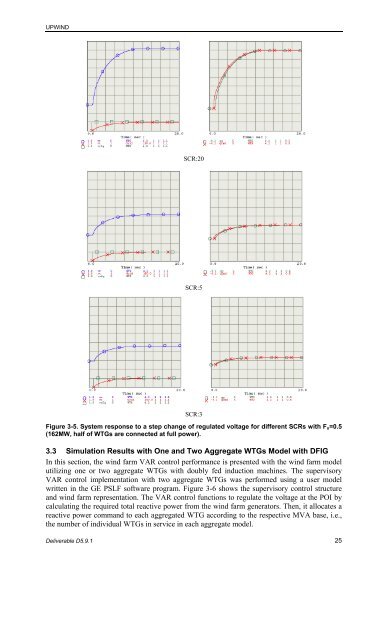
Figure 3-5. System resp<strong>on</strong>se to a step change <str<strong>on</strong>g>of</str<strong>on</strong>g> regulated voltage for different SCRs with Fn=0.5<br />
(162MW, half <str<strong>on</strong>g>of</str<strong>on</strong>g> WTGs are c<strong>on</strong>nected at full power).<br />
3.3 Simulati<strong>on</strong> Results with One and Two Aggregate WTGs Model with DFIG<br />
In this secti<strong>on</strong>, the wind farm <strong>VAR</strong> c<strong>on</strong>trol performance is presented with the wind farm model<br />
utilizing <strong>on</strong>e or two aggregate WTGs with doubly fed inducti<strong>on</strong> machines. The supervisory<br />
<strong>VAR</strong> c<strong>on</strong>trol implementati<strong>on</strong> with two aggregate WTGs was performed using a user model<br />
written in the GE PSLF s<str<strong>on</strong>g>of</str<strong>on</strong>g>tware program. Figure 3-6 shows the supervisory c<strong>on</strong>trol structure<br />
and wind farm representati<strong>on</strong>. The <strong>VAR</strong> c<strong>on</strong>trol functi<strong>on</strong>s to regulate the voltage at the POI by<br />
calculating the required total reactive power from the wind farm generators. Then, it allocates a<br />
reactive power command to each aggregated WTG according to the respective MVA base, i.e.,<br />
the number <str<strong>on</strong>g>of</str<strong>on</strong>g> individual WTGs in service in each aggregate model.<br />
Deliverable D5.9.1 25


