Impact of Drivetrain on Wind Farm VAR Control - Upwind
Impact of Drivetrain on Wind Farm VAR Control - Upwind
Impact of Drivetrain on Wind Farm VAR Control - Upwind
You also want an ePaper? Increase the reach of your titles
YUMPU automatically turns print PDFs into web optimized ePapers that Google loves.
UPWIND<br />
3.1.3 <strong>Wind</strong> <strong>Farm</strong> <strong>VAR</strong> C<strong>on</strong>trol Loop<br />
The <strong>VAR</strong> c<strong>on</strong>trol loop includes the WTG voltage and reactive power c<strong>on</strong>trol loops. As<br />
menti<strong>on</strong>ed before, the WTG voltage c<strong>on</strong>trol time resp<strong>on</strong>se is fast, and thus the reactive power<br />
c<strong>on</strong>trol integral gain plays a main role in the design <str<strong>on</strong>g>of</str<strong>on</strong>g> the <strong>VAR</strong> c<strong>on</strong>trol (namely, the PI<br />
Ki Kp<br />
c<strong>on</strong>troller in Figure 3-1). The PI c<strong>on</strong>troller transfer functi<strong>on</strong> can be written as ( 1+<br />
s)<br />
.<br />
s Ki<br />
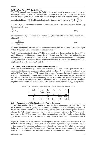
The ratio Kp/Ki is determined such that to cancel the effect <str<strong>on</strong>g>of</str<strong>on</strong>g> the reactive power c<strong>on</strong>trol loop<br />
time c<strong>on</strong>stant Tq, i.e.,<br />
K p<br />
= Tq<br />
(3.5)<br />
K<br />
i<br />
Having the value Kp/Ki adjusted as in equati<strong>on</strong> (3.5), the wind <strong>VAR</strong> c<strong>on</strong>trol time c<strong>on</strong>stant can be<br />
obtained by [4]:<br />
T<br />
V<br />
POI<br />
var =<br />
(3.6)<br />
X grid ⋅ K i<br />
It can be inferred that for the same <strong>VAR</strong> c<strong>on</strong>trol time c<strong>on</strong>stant, the value <str<strong>on</strong>g>of</str<strong>on</strong>g> Ki would be higher<br />
with a str<strong>on</strong>ger grid, i.e., with higher short circuit ratio.<br />
With Fn representing the fracti<strong>on</strong> <str<strong>on</strong>g>of</str<strong>on</strong>g> WTGs in the wind farm that are <strong>on</strong>line, the factor 1/Fn is<br />
needed in the c<strong>on</strong>trol loop to counteract the reducti<strong>on</strong> <str<strong>on</strong>g>of</str<strong>on</strong>g> wind farm MVA base and the increase<br />
<str<strong>on</strong>g>of</str<strong>on</strong>g> equivalent pu WTG reactive power. This would recover the desired system c<strong>on</strong>trol resp<strong>on</strong>se.<br />
The Fn adjustment is possible when the number <str<strong>on</strong>g>of</str<strong>on</strong>g> c<strong>on</strong>nected WTGs “N” can be measured in the<br />
implementati<strong>on</strong> <str<strong>on</strong>g>of</str<strong>on</strong>g> the wind <strong>VAR</strong> c<strong>on</strong>trol.<br />
3.2 <strong>Wind</strong> <strong>VAR</strong> C<strong>on</strong>trol Parameters Determinati<strong>on</strong><br />
From the aforementi<strong>on</strong>ed guidelines, the different wind <strong>VAR</strong> c<strong>on</strong>trol parameters for the<br />
c<strong>on</strong>sidered test system were determined and are listed in Table 3-1 for different grid short circuit<br />
ratios (SCRs). The wind farm <strong>VAR</strong> c<strong>on</strong>trol time c<strong>on</strong>stant (Tvar) was chosen as 3 sec<strong>on</strong>ds, and the<br />
reactive power c<strong>on</strong>trol time c<strong>on</strong>stant (Tq) <str<strong>on</strong>g>of</str<strong>on</strong>g> the aggregate WTG without the <strong>VAR</strong> c<strong>on</strong>trol was<br />
chosen as 0.5 sec<strong>on</strong>ds. It is worth menti<strong>on</strong>ing that the parameters were determined assuming that<br />
all individual WTGs are <strong>on</strong>line. With a fracti<strong>on</strong> <str<strong>on</strong>g>of</str<strong>on</strong>g> the WTGs <strong>on</strong>line, the c<strong>on</strong>trol parameters<br />
might be recalculated if the variati<strong>on</strong> <str<strong>on</strong>g>of</str<strong>on</strong>g> the total system per unit impedance Xtotal is significant.<br />
Table 3-1 <strong>VAR</strong> C<strong>on</strong>trol Parameters with DFIG machine for Different SCRs<br />
SCR Tvar<br />
Tq<br />
Kq Kp Ki<br />
(sec) (sec)<br />
20 3 0.5 0.5 3.33 6.66<br />
5 3 0.5 0.82 0.833 1.66<br />
3 3 0.5 1.08 0.5 1.0<br />
3.2.1 Resp<strong>on</strong>se to a WTG Step Reactive Power Command<br />
This secti<strong>on</strong> examines the WTG resp<strong>on</strong>se to a step reactive power command (Qcmd). The amount<br />
<str<strong>on</strong>g>of</str<strong>on</strong>g> WTG reactive power (Qg) required to change the voltage at the POI is inversely proporti<strong>on</strong>al<br />
to the total system impedance. In other words, for the same WTG reactive power command<br />
change, the POI voltage variati<strong>on</strong> would be lower for str<strong>on</strong>ger systems. If the WTG is directly<br />
c<strong>on</strong>nected to the POI bus with a system short circuit ratio <str<strong>on</strong>g>of</str<strong>on</strong>g> 20, a 20% Qg change is needed for<br />
1% voltage variati<strong>on</strong> at the POI, whereas a 3% Qg change is needed with a short circuit ratio <str<strong>on</strong>g>of</str<strong>on</strong>g><br />
3.<br />
Figure 3-2 shows the WTG generated reactive power resp<strong>on</strong>se as well as the resp<strong>on</strong>se <str<strong>on</strong>g>of</str<strong>on</strong>g> both<br />
the WTG terminal voltage (blue line with o marks) and the regulated voltage at the POI (red line<br />
with x marks). The minimum and maximum value <str<strong>on</strong>g>of</str<strong>on</strong>g> the y-axis are shown below the x-axis as<br />
indicated in the lowest plot. The magnitude <str<strong>on</strong>g>of</str<strong>on</strong>g> the step reactive power command is lower with<br />
lower short circuit ratio so that the WTG terminal voltage does not exceed its maximum limit.<br />
Deliverable D5.9.1 19


