

Impact of Drivetrain on Wind Farm VAR Control - Upwind
Impact of Drivetrain on Wind Farm VAR Control - Upwind
Impact of Drivetrain on Wind Farm VAR Control - Upwind

You also want an ePaper? Increase the reach of your titles
YUMPU automatically turns print PDFs into web optimized ePapers that Google loves.
UPWIND<br />
3. <strong>Wind</strong> <strong>Farm</strong> <strong>VAR</strong> C<strong>on</strong>trol for WTGs with Power Electr<strong>on</strong>ics<br />
for Grid Interface<br />
This secti<strong>on</strong> presents the design <str<strong>on</strong>g>of</str<strong>on</strong>g> a wind farm <strong>VAR</strong> c<strong>on</strong>trol for wind turbines utilizing power<br />
electr<strong>on</strong>ics for the grid interface. The focus will be <strong>on</strong> doubly fed inducti<strong>on</strong> generator (DFIG)<br />
machines. Representati<strong>on</strong> <str<strong>on</strong>g>of</str<strong>on</strong>g> the wind farm by <strong>on</strong>e or two aggregate WTGs is performed. The<br />
electrical system described in Secti<strong>on</strong> 2 is c<strong>on</strong>sidered for the design verificati<strong>on</strong>. Different<br />
scenarios <str<strong>on</strong>g>of</str<strong>on</strong>g> the number <str<strong>on</strong>g>of</str<strong>on</strong>g> c<strong>on</strong>nected wind turbines in the wind farm and different wind farm<br />
power levels are investigated to identify the main factors that have critical impact <strong>on</strong> the wind<br />
farm <strong>VAR</strong> c<strong>on</strong>trol performance. This provides insight into the design procedure to be followed<br />
c<strong>on</strong>sidering the variati<strong>on</strong> <str<strong>on</strong>g>of</str<strong>on</strong>g> wind farm operating c<strong>on</strong>diti<strong>on</strong>s and system parameters whilst<br />
maintaining the desired system voltage resp<strong>on</strong>se.<br />
3.1 <strong>Wind</strong> <strong>Farm</strong> <strong>VAR</strong> Design Guidelines<br />
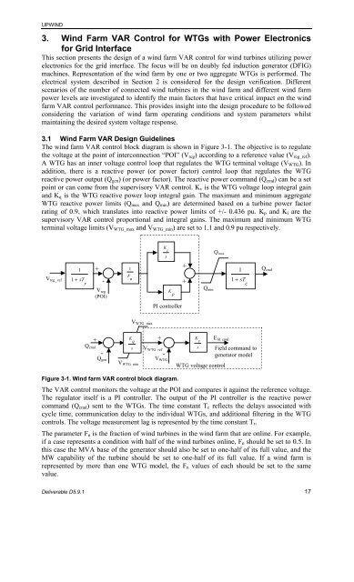
The wind farm <strong>VAR</strong> c<strong>on</strong>trol block diagram is shown in Figure 3-1. The objective is to regulate<br />
the voltage at the point <str<strong>on</strong>g>of</str<strong>on</strong>g> interc<strong>on</strong>necti<strong>on</strong> “POI” (Vreg) according to a reference value (Vreg_ref).<br />
A WTG has an inner voltage c<strong>on</strong>trol loop that regulates the WTG terminal voltage (VWTG). In<br />
additi<strong>on</strong>, there is a reactive power (or power factor) c<strong>on</strong>trol loop that regulates the WTG<br />
reactive power output (Qgen) (or power factor). The reactive power command (Qcmd) can be a set<br />
point or can come from the supervisory <strong>VAR</strong> c<strong>on</strong>trol. Kv is the WTG voltage loop integral gain<br />
and Kq is the WTG reactive power loop integral gain. The maximum and minimum aggregate<br />
WTG reactive power limits (Qmax and Qmin) are determined based <strong>on</strong> a turbine power factor<br />
rating <str<strong>on</strong>g>of</str<strong>on</strong>g> 0.9, which translates into reactive power limits <str<strong>on</strong>g>of</str<strong>on</strong>g> +/- 0.436 pu. Kp and Ki are the<br />
supervisory <strong>VAR</strong> c<strong>on</strong>trol proporti<strong>on</strong>al and integral gains. The maximum and minimum WTG<br />
terminal voltage limits (VWTG_max and VWTG_min) are set to 1.1 and 0.9 pu respectively.<br />
Vreg_ ref<br />
1<br />
1 + sT<br />
r<br />
+<br />
-<br />
Vreg<br />
(POI)<br />
+<br />
Qcmd<br />
-<br />
Qgen<br />
1<br />
F<br />
n<br />
K<br />
q<br />
s<br />
VWTG_min<br />
VWTG_max<br />
+<br />
VWTG_ref<br />
K<br />
i<br />
s<br />
-<br />
VWTG<br />
K<br />
p<br />
PI c<strong>on</strong>troller<br />
Figure 3-1. <strong>Wind</strong> farm <strong>VAR</strong> c<strong>on</strong>trol block diagram.<br />
Deliverable D5.9.1 17<br />
+<br />
Qmax<br />
+ 1 + sT<br />
c<br />
Qmin<br />
K Efd_cmd<br />
v<br />
s Field command to<br />
generator model<br />
WTG voltage c<strong>on</strong>trol<br />
The <strong>VAR</strong> c<strong>on</strong>trol m<strong>on</strong>itors the voltage at the POI and compares it against the reference voltage.<br />
The regulator itself is a PI c<strong>on</strong>troller. The output <str<strong>on</strong>g>of</str<strong>on</strong>g> the PI c<strong>on</strong>troller is the reactive power<br />
command (Qcmd) sent to the WTGs. The time c<strong>on</strong>stant Tc reflects the delays associated with<br />
cycle time, communicati<strong>on</strong> delay to the individual WTGs, and additi<strong>on</strong>al filtering in the WTG<br />
c<strong>on</strong>trols. The voltage measurement lag is represented by the time c<strong>on</strong>stant Tr.<br />
The parameter Fn is the fracti<strong>on</strong> <str<strong>on</strong>g>of</str<strong>on</strong>g> wind turbines in the wind farm that are <strong>on</strong>line. For example,<br />
if a case represents a c<strong>on</strong>diti<strong>on</strong> with half <str<strong>on</strong>g>of</str<strong>on</strong>g> the wind turbines <strong>on</strong>line, Fn should be set to 0.5. In<br />
this case the MVA base <str<strong>on</strong>g>of</str<strong>on</strong>g> the generator should also be set to <strong>on</strong>e-half <str<strong>on</strong>g>of</str<strong>on</strong>g> its full value, and the<br />
MW capability <str<strong>on</strong>g>of</str<strong>on</strong>g> the turbine should be set to <strong>on</strong>e-half <str<strong>on</strong>g>of</str<strong>on</strong>g> its full value. If a wind farm is<br />
represented by more than <strong>on</strong>e WTG model, the Fn values <str<strong>on</strong>g>of</str<strong>on</strong>g> each should be set to the same<br />
value.<br />
1<br />
Qcmd


