

Impact of Drivetrain on Wind Farm VAR Control - Upwind
Impact of Drivetrain on Wind Farm VAR Control - Upwind
Impact of Drivetrain on Wind Farm VAR Control - Upwind

Create successful ePaper yourself
Turn your PDF publications into a flip-book with our unique Google optimized e-Paper software.
UPWIND<br />
reactance (Xgrid). The ratio Kp/Ki is chosen to cancel the reactive power c<strong>on</strong>trol loop time<br />
c<strong>on</strong>stant Tq. This can be interpreted as follows:<br />
K p<br />
= Tq<br />
(5.4)<br />
K i<br />
K<br />
i<br />
=<br />
T<br />
var<br />
1<br />
⋅ X<br />
grid<br />
(5.5)<br />
The wind farm <strong>VAR</strong> c<strong>on</strong>troller parameters are shown in Table 4-6. The system resp<strong>on</strong>se to a<br />
step change <str<strong>on</strong>g>of</str<strong>on</strong>g> the reference voltage at the POI (Vrfg) is shown in Figure 4-10 with all WTGs<br />
in service and in Figure 4-11 with half <str<strong>on</strong>g>of</str<strong>on</strong>g> the WTGs in service. Vreg is the regulated voltage at<br />
the POI and Vt is the WTG terminal voltage. With all WTGs c<strong>on</strong>nected, the step voltage<br />
magnitude was 0.015 pu where it was 0.01 pu with half <str<strong>on</strong>g>of</str<strong>on</strong>g> the WTGs in service so that the<br />
WTG reactive power does not exceed the machine maximum limit. A reas<strong>on</strong>able time<br />
resp<strong>on</strong>se (settling time <str<strong>on</strong>g>of</str<strong>on</strong>g> the order <str<strong>on</strong>g>of</str<strong>on</strong>g> a few sec<strong>on</strong>ds) <str<strong>on</strong>g>of</str<strong>on</strong>g> the POI voltage with the desired time<br />
c<strong>on</strong>stant was obtained.<br />
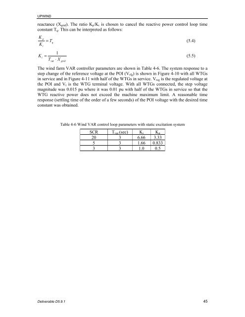
Table 4-6 <strong>Wind</strong> <strong>VAR</strong> c<strong>on</strong>trol loop parameters with static excitati<strong>on</strong> system<br />
SCR Tvar (sec) Ki Kp<br />
20 3 6.66 3.33<br />
5 3 1.66 0.833<br />
3 3 1.0 0.5<br />
Deliverable D5.9.1 45


