

Impact of Drivetrain on Wind Farm VAR Control - Upwind
Impact of Drivetrain on Wind Farm VAR Control - Upwind
Impact of Drivetrain on Wind Farm VAR Control - Upwind

Create successful ePaper yourself
Turn your PDF publications into a flip-book with our unique Google optimized e-Paper software.
UPWIND<br />
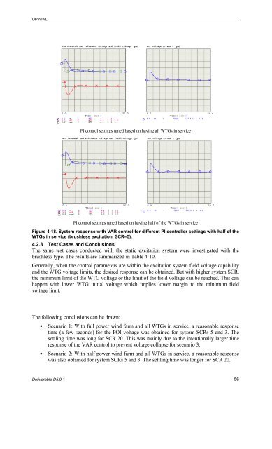
PI c<strong>on</strong>trol settings tuned based <strong>on</strong> having all WTGs in service<br />
PI c<strong>on</strong>trol settings tuned based <strong>on</strong> having half <str<strong>on</strong>g>of</str<strong>on</strong>g> the WTGs in service<br />
Figure 4-18. System resp<strong>on</strong>se with <strong>VAR</strong> c<strong>on</strong>trol for different PI c<strong>on</strong>troller settings with half <str<strong>on</strong>g>of</str<strong>on</strong>g> the<br />
WTGs in service (brushless excitati<strong>on</strong>, SCR=5).<br />
4.2.3 Test Cases and C<strong>on</strong>clusi<strong>on</strong>s<br />
The same test cases c<strong>on</strong>ducted with the static excitati<strong>on</strong> system were investigated with the<br />
brushless-type. The results are summarized in Table 4-10.<br />
Generally, when the c<strong>on</strong>trol parameters are within the excitati<strong>on</strong> system field voltage capability<br />
and the WTG voltage limits, the desired resp<strong>on</strong>se can be obtained. But with higher system SCR,<br />
the minimum limit <str<strong>on</strong>g>of</str<strong>on</strong>g> the WTG voltage or the limit <str<strong>on</strong>g>of</str<strong>on</strong>g> the field voltage can be reached. This can<br />
happen with lower WTG initial voltage which implies lower margin to the minimum field<br />
voltage limit.<br />
The following c<strong>on</strong>clusi<strong>on</strong>s can be drawn:<br />
• Scenario 1: With full power wind farm and all WTGs in service, a reas<strong>on</strong>able resp<strong>on</strong>se<br />
time (a few sec<strong>on</strong>ds) for the POI voltage was obtained for system SCRs 5 and 3. The<br />
settling time was l<strong>on</strong>g for SCR 20. This was mainly due to the intenti<strong>on</strong>ally larger time<br />
resp<strong>on</strong>se <str<strong>on</strong>g>of</str<strong>on</strong>g> the <strong>VAR</strong> c<strong>on</strong>trol to prevent voltage collapse for scenario 3.<br />
• Scenario 2: With half power wind farm and all WTGs in service, a reas<strong>on</strong>able resp<strong>on</strong>se<br />
was also obtained for system SCRs 5 and 3. The settling time was l<strong>on</strong>ger for SCR 20.<br />
Deliverable D5.9.1 56


