

Impact of Drivetrain on Wind Farm VAR Control - Upwind
Impact of Drivetrain on Wind Farm VAR Control - Upwind
Impact of Drivetrain on Wind Farm VAR Control - Upwind

Create successful ePaper yourself
Turn your PDF publications into a flip-book with our unique Google optimized e-Paper software.
UPWIND<br />
4.2 Brushless-Type Excitati<strong>on</strong> System<br />
A brushless-type excitati<strong>on</strong> system has a rotating diode bridge rectifier <strong>on</strong> the same shaft with<br />
the exciter armature and the main generator field. Therefore, the need for slip ring and brushes is<br />
eliminated. The DC output from the rotating rectifier is directly fed to the main generator field.<br />
The stati<strong>on</strong>ary field voltage <str<strong>on</strong>g>of</str<strong>on</strong>g> the exciter is c<strong>on</strong>trolled and c<strong>on</strong>sequently the AC exciter voltage<br />
is regulated, which in turn c<strong>on</strong>trols the DC field <str<strong>on</strong>g>of</str<strong>on</strong>g> the main generator through the diode bridge<br />
rectifier. The excitati<strong>on</strong> system time resp<strong>on</strong>se has an impact <strong>on</strong> the system resp<strong>on</strong>se and the<br />
design <str<strong>on</strong>g>of</str<strong>on</strong>g> the <strong>VAR</strong> c<strong>on</strong>trol. It is supplied from the main generator voltage and, therefore, is<br />
affected by grid disturbance events.<br />
4.2.1 Performance <str<strong>on</strong>g>of</str<strong>on</strong>g> Brushless-Type Excitati<strong>on</strong> System<br />
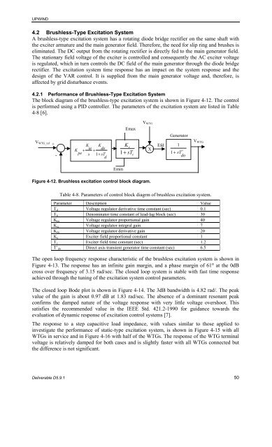
The block diagram <str<strong>on</strong>g>of</str<strong>on</strong>g> the brushless-type excitati<strong>on</strong> system is shown in Figure 4-12. The c<strong>on</strong>trol<br />
is performed using a PID c<strong>on</strong>troller. The parameters <str<strong>on</strong>g>of</str<strong>on</strong>g> the excitati<strong>on</strong> system are listed in Table<br />
4-8 [6].<br />
VWTG_ref<br />
+<br />
-<br />
K<br />
pe<br />
+<br />
K K<br />
ie<br />
+<br />
de<br />
s 1+<br />
sT<br />
d<br />
Emin<br />
Emax<br />
Ke<br />
1+<br />
sT<br />
e<br />
X Efd<br />
Generator<br />
Deliverable D5.9.1 50<br />
VWTG<br />
Figure 4-12. Brushless excitati<strong>on</strong> c<strong>on</strong>trol block diagram.<br />
1<br />
1 + s T′<br />
do<br />
VWTG<br />
Table 4-8. Parameters <str<strong>on</strong>g>of</str<strong>on</strong>g> c<strong>on</strong>trol block diagrm <str<strong>on</strong>g>of</str<strong>on</strong>g> brushless excitati<strong>on</strong> system.<br />
Parameter Descripti<strong>on</strong> Value<br />
Td Voltage regulator derivative time c<strong>on</strong>stant (sec) 0.1<br />
Tb Denominator time c<strong>on</strong>stant <str<strong>on</strong>g>of</str<strong>on</strong>g> lead-lag block (sec) 30<br />
Kpe Voltage regulator proporti<strong>on</strong>al gain 40<br />
Kie Voltage regulator integral gain 7<br />
Kde Voltage regulator derivative gain 20<br />
Ke Exciter field proporti<strong>on</strong>al c<strong>on</strong>stant 1<br />
Te Exciter field time c<strong>on</strong>stant (sec) 1.2<br />
T’do Direct axis transient generator time c<strong>on</strong>stant (sec) 6.5<br />
The open loop frequency resp<strong>on</strong>se characteristic <str<strong>on</strong>g>of</str<strong>on</strong>g> the brushless excitati<strong>on</strong> system is shown in<br />
Figure 4-13. The resp<strong>on</strong>se has an infinite gain margin, and a phase margin <str<strong>on</strong>g>of</str<strong>on</strong>g> 61° at the 0dB<br />
cross over frequency <str<strong>on</strong>g>of</str<strong>on</strong>g> 3.15 rad/sec. The closed loop system is stable with fast time resp<strong>on</strong>se<br />
achieved through the tuning <str<strong>on</strong>g>of</str<strong>on</strong>g> the excitati<strong>on</strong> system c<strong>on</strong>trol parameters.<br />
The closed loop Bode plot is shown in Figure 4-14. The 3dB bandwidth is 4.82 rad/. The peak<br />
value <str<strong>on</strong>g>of</str<strong>on</strong>g> the gain is about 0.97 dB at 1.83 rad/sec. The absence <str<strong>on</strong>g>of</str<strong>on</strong>g> a dominant res<strong>on</strong>ant peak<br />
c<strong>on</strong>firms the damped nature <str<strong>on</strong>g>of</str<strong>on</strong>g> the voltage resp<strong>on</strong>se with very little voltage overshoot. This<br />
satisfies the recommended value in the IEEE Std. 421.2-1990 for guidance towards the<br />
evaluati<strong>on</strong> <str<strong>on</strong>g>of</str<strong>on</strong>g> dynamic resp<strong>on</strong>se <str<strong>on</strong>g>of</str<strong>on</strong>g> excitati<strong>on</strong> c<strong>on</strong>trol systems [7].<br />
The resp<strong>on</strong>se to a step capacitive load impedance, with values similar to those applied to<br />
investigate the performance <str<strong>on</strong>g>of</str<strong>on</strong>g> static-type excitati<strong>on</strong> system, is shown in Figure 4-15 with all<br />
WTGs in service and in Figure 4-16 with half <str<strong>on</strong>g>of</str<strong>on</strong>g> the WTGs. The resp<strong>on</strong>se <str<strong>on</strong>g>of</str<strong>on</strong>g> the WTG terminal<br />
voltage is relatively damped for both cases and is slightly faster with all WTGs c<strong>on</strong>nected but<br />
the difference is not significant.


