

Impact of Drivetrain on Wind Farm VAR Control - Upwind
Impact of Drivetrain on Wind Farm VAR Control - Upwind
Impact of Drivetrain on Wind Farm VAR Control - Upwind

You also want an ePaper? Increase the reach of your titles
YUMPU automatically turns print PDFs into web optimized ePapers that Google loves.
UPWIND<br />
available wind power is less than rated, the blades are set at minimum pitch to maximize the<br />
mechanical power. The blade positi<strong>on</strong> actuators are rate limited and there is a time c<strong>on</strong>stant<br />
associated with the translati<strong>on</strong> <str<strong>on</strong>g>of</str<strong>on</strong>g> blade angle to mechanical output. The dynamics <str<strong>on</strong>g>of</str<strong>on</strong>g> the pitch<br />
c<strong>on</strong>trol are moderately fast, and can have significant impact <strong>on</strong> dynamic simulati<strong>on</strong> results. The<br />
turbine c<strong>on</strong>trol acts to smooth out electrical power fluctuati<strong>on</strong>s due to variati<strong>on</strong>s in shaft power.<br />
This is achieved by allowing the machine speed to vary around reference speed where the inertia<br />
<str<strong>on</strong>g>of</str<strong>on</strong>g> the machine functi<strong>on</strong>s as a buffer to mechanical power variati<strong>on</strong>s.<br />
2. Test System Descripti<strong>on</strong><br />
2.1 <strong>Wind</strong> Turbine Generator Modelling for Load Flow<br />
<strong>Wind</strong> farms normally c<strong>on</strong>sist <str<strong>on</strong>g>of</str<strong>on</strong>g> a large number <str<strong>on</strong>g>of</str<strong>on</strong>g> individual wind turbine generators (WTGs).<br />
The wind farm model may c<strong>on</strong>sist <str<strong>on</strong>g>of</str<strong>on</strong>g> a detailed representati<strong>on</strong> <str<strong>on</strong>g>of</str<strong>on</strong>g> each WTG and the collector<br />
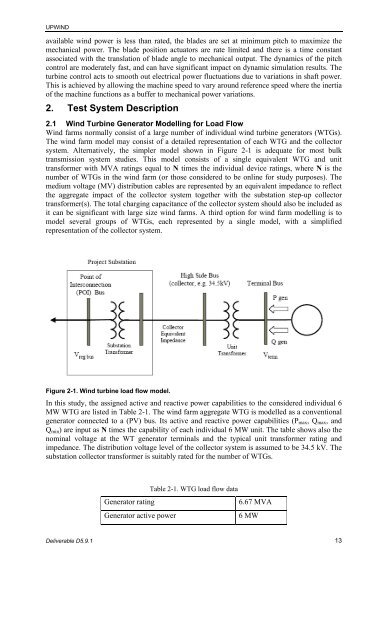
system. Alternatively, the simpler model shown in Figure 2-1 is adequate for most bulk<br />
transmissi<strong>on</strong> system studies. This model c<strong>on</strong>sists <str<strong>on</strong>g>of</str<strong>on</strong>g> a single equivalent WTG and unit<br />
transformer with MVA ratings equal to N times the individual device ratings, where N is the<br />
number <str<strong>on</strong>g>of</str<strong>on</strong>g> WTGs in the wind farm (or those c<strong>on</strong>sidered to be <strong>on</strong>line for study purposes). The<br />
medium voltage (MV) distributi<strong>on</strong> cables are represented by an equivalent impedance to reflect<br />
the aggregate impact <str<strong>on</strong>g>of</str<strong>on</strong>g> the collector system together with the substati<strong>on</strong> step-up collector<br />
transformer(s). The total charging capacitance <str<strong>on</strong>g>of</str<strong>on</strong>g> the collector system should also be included as<br />
it can be significant with large size wind farms. A third opti<strong>on</strong> for wind farm modelling is to<br />
model several groups <str<strong>on</strong>g>of</str<strong>on</strong>g> WTGs, each represented by a single model, with a simplified<br />
representati<strong>on</strong> <str<strong>on</strong>g>of</str<strong>on</strong>g> the collector system.<br />
Figure 2-1. <strong>Wind</strong> turbine load flow model.<br />
In this study, the assigned active and reactive power capabilities to the c<strong>on</strong>sidered individual 6<br />
MW WTG are listed in Table 2-1. The wind farm aggregate WTG is modelled as a c<strong>on</strong>venti<strong>on</strong>al<br />
generator c<strong>on</strong>nected to a (PV) bus. Its active and reactive power capabilities (Pmax, Qmax, and<br />
Qmin) are input as N times the capability <str<strong>on</strong>g>of</str<strong>on</strong>g> each individual 6 MW unit. The table shows also the<br />
nominal voltage at the WT generator terminals and the typical unit transformer rating and<br />
impedance. The distributi<strong>on</strong> voltage level <str<strong>on</strong>g>of</str<strong>on</strong>g> the collector system is assumed to be 34.5 kV. The<br />
substati<strong>on</strong> collector transformer is suitably rated for the number <str<strong>on</strong>g>of</str<strong>on</strong>g> WTGs.<br />
Table 2-1. WTG load flow data<br />
Generator rating 6.67 MVA<br />
Generator active power 6 MW<br />
Deliverable D5.9.1 13


