Manual TCIP 603-03 TCIP SRV 603-0 - Siedle
Manual TCIP 603-03 TCIP SRV 603-0 - Siedle
Manual TCIP 603-03 TCIP SRV 603-0 - Siedle
Create successful ePaper yourself
Turn your PDF publications into a flip-book with our unique Google optimized e-Paper software.
<strong>Manual</strong> <strong>TCIP</strong> <strong>6<strong>03</strong></strong>-<strong>03</strong><br />
Each door can be assigned to a maximum of two input readers and two output readers. These readers are linked by either<br />
a logical „AND“ or „OR“.<br />
If readers are linked by a logical „AND“, the period during which a login must be performed at both readers in order to<br />
validate the login is specified in the „Timeout time“ field. If this time expires before both readers have signalled a valid<br />
login, the process must be started again from the beginning.<br />
It is possible to assign a door to a door sensor. This is used to signal the „Door open“ and „Door shut“ status. If no door<br />
sensor has been assigned, every login/logout is evaluated as an entry/exit.<br />
Via the door button, which can be assigned to one door, users have the possibility to actuate the door relay. A time profile<br />
must be assigned to the door button which regulates the times at which this button is active. In addition, the door relay<br />
can also be actuated via the web user interface.<br />
The door relay is the output which is actuated when the door needs to be unlocked. By means of a switching time, it is<br />
possible to determine the period for which the relay should be actuated.<br />
The time profile determines at which times the door relay needs to be permanently actuated.<br />
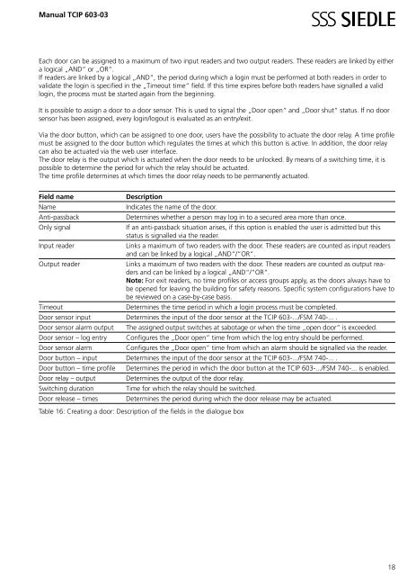
Field name Description<br />
Name Indicates the name of the door.<br />
Anti-passback Determines whether a person may log in to a secured area more than once.<br />
Only signal If an anti-passback situation arises, if this option is enabled the user is admitted but this<br />
status is signalled via the reader.<br />
Input reader Links a maximum of two readers with the door. These readers are counted as input readers<br />
and can be linked by a logical „AND“/“OR“.<br />
Output reader Links a maximum of two readers with the door. These readers are counted as output readers<br />
and can be linked by a logical „AND“/“OR“.<br />
Note: For exit readers, no time profiles or access groups apply, as the doors always have to<br />
be opened for leaving the building for safety reasons. Specific system configurations have to<br />
be reviewed on a case-by-case basis.<br />
Timeout Determines the time period in which a login process must be completed.<br />
Door sensor input Determines the input of the door sensor at the <strong>TCIP</strong> <strong>6<strong>03</strong></strong>-.../FSM 740-... .<br />
Door sensor alarm output The assigned output switches at sabotage or when the time „open door“ is exceeded.<br />
Door sensor – log entry Configures the „Door open“ time from which the log entry should be performed.<br />
Door sensor alarm Configures the „Door open“ time from which an alarm should be signalled via the reader.<br />
Door button – input Determines the input of the door sensor at the <strong>TCIP</strong> <strong>6<strong>03</strong></strong>-.../FSM 740-... .<br />
Door button – time profile Determines the period in which the door button at the <strong>TCIP</strong> <strong>6<strong>03</strong></strong>-.../FSM 740-... is enabled.<br />
Door relay – output Determines the output of the door relay.<br />
Switching duration Time for which the relay should be switched.<br />
Door release – times Determines the period during which the door release may be actuated.<br />
Table 16: Creating a door: Description of the fields in the dialogue box<br />
18


