Martis Valley Groundwater Management Plan - Placer County Water ...
Martis Valley Groundwater Management Plan - Placer County Water ...
Martis Valley Groundwater Management Plan - Placer County Water ...

You also want an ePaper? Increase the reach of your titles
YUMPU automatically turns print PDFs into web optimized ePapers that Google loves.
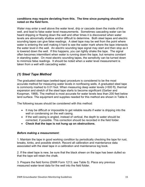
conditions may require deviating from this. The time since pumping should be<br />
noted on the field form.<br />
<strong>Water</strong> may enter a well above the water level, drip or cascade down the inside of the<br />
well, and lead to false water level measurements. Sometimes cascading water can be<br />
heard dripping or flowing down the well and other times it is discovered when water<br />
levels are abnormally shallow and/or difficult to determine. Both steel tapes and electric<br />
sounding tapes can give false readings. A steel tape may be wet from the point where<br />
water is entering the well making it hard to see the water mark where the tape intersects<br />
the water level in the well. An electric sounding tape signal may start and then stop as it<br />
is lowered down the well. If this happens, you can lightly shake the tape. The signal<br />
often becomes intermittent when water is running down the tape, but remains constant<br />
in standing water. On most electric sounding tapes, the sensitivity can be turned down<br />
to minimize false readings. It should be noted when a water level measurement is<br />
taken from a well with cascading water.<br />
(1) Steel Tape Method<br />
The graduated steel-tape (wetted-tape) procedure is considered to be the most<br />
accurate method for measuring water levels in nonflowing wells. A graduated steel tape<br />
is commonly marked to 0.01 foot. When measuring deep water levels (>500 ft), thermal<br />
expansion and stretch of the steel tape starts to become significant (Garber and<br />
Koopman, 1968). The method is most accurate for water levels less than 200 feet below<br />
land surface. The equipment and supplies needed for this method are shown in Table 4.<br />
The following issues should be considered with this method:<br />
• It may be difficult or impossible to get reliable results if water is dripping into the<br />
well or condensing on the well casing.<br />
• If the well casing is angled, instead of vertical, the depth to water should be<br />
corrected, if possible. This correction should be recorded in the field folder.<br />
• Check that the tape is not hung up on obstructions.<br />
Before making a measurement:<br />
1. Maintain the tape in good working condition by periodically checking the tape for rust,<br />
breaks, kinks, and possible stretch. Record all calibration and maintenance data<br />
associated with the steel tape in a calibration and maintenance log book.<br />
2. If the steel tape is new, be sure that the black sheen on the tape has been dulled so<br />
that the tape will retain the chalk.<br />
3. Prepare the field forms (DWR Form 1213; see Table 5). Place any previous<br />
measured water-level data for the well into the field folder.<br />
DWR <strong>Groundwater</strong> Elevation Monitoring Guidelines 15