RK06/RK07 Disk Drive User's Manual - Trailing-Edge
RK06/RK07 Disk Drive User's Manual - Trailing-Edge
RK06/RK07 Disk Drive User's Manual - Trailing-Edge
Create successful ePaper yourself
Turn your PDF publications into a flip-book with our unique Google optimized e-Paper software.
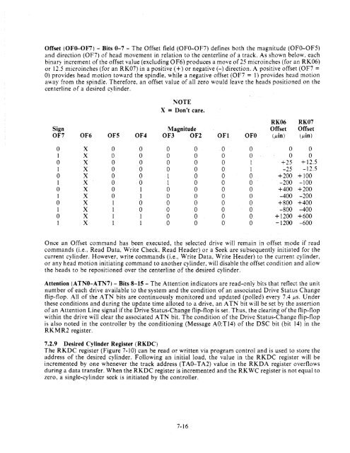
Offset (OFO-OF7) - Bits 0-7 - The Offset field (OFO-OF7) defines both the magnitude (OFO-OF5)<br />
and direction (OF7) of head movement in relation to the centerline of a track. As shown below. each<br />
binary increment of the offset value (excluding 0 F6) produces a move of 25 microinches (for an <strong>RK06</strong>)<br />
or 12.5 microinches (for an <strong>RK07</strong>) in a positive (+) or negative (-) direction. A positive offset (OF7 =<br />
0) provides head motion toward the spindle. while a negative offset (OF7 = 1) provides head motion<br />
away from the spindle. Therefore. an offset value of all zero would leave the heads positioned on the<br />
centerline of a desired cylinder.<br />
NOTE<br />
X = Don't care.<br />
<strong>RK06</strong> <strong>RK07</strong><br />
Sign Magnitude Offset Offset<br />
OF7 OF6 OF5 OF4 OF3 OF2 OFI OFO (,uin) (,uin)<br />
0 X 0 0 0 0 0 0 0 0<br />
1 X 0 0 0 0 0 0 0 0<br />
0 X 0 0 0 0 0 1 +25 + 12.5<br />
1 X 0 0 0 0 0 1 -25 -12.5<br />
0 X 0 0 1 0 0 0 +200 + 100<br />
1 X 0 0 1 0 0 0 -200 -100<br />
0 X 0 1 0 0 0 0 +400 +200<br />
1 X 0 1 0 0 0 0 -400 -200<br />
0 X 1 0 0 0 0 0 +800 +400<br />
1 X 1 0 0 0 0 0 -800 -400<br />
0 X 1 1 0 0 0 0 + 1200 +600<br />
1 X 1 1 0 0 0 0 -1200 -600<br />
Once an Offset command has been executed, the selected drive will remain in offset mode if read<br />
commands (i.e., Read Data, Write Check, Read Header) or a Seek are subsequently initiated for the<br />
current cylinder. However, write commands (i.e., Write Data, Write Header) to the current cylinder.<br />
or any head motion initiating command to another cylinder, will disable the offset condition and allow<br />
the heads to be repositioned over the centerline of the desired cylinder.<br />
Attention (ATNO-ATN7) - Bits 8-15 - The Attention indicators are read-onlY bits that reflect the unit<br />
number of each drive available to the 'system and the condition of an associated <strong>Drive</strong> Status Change<br />
flip-flop. All of the A TN bits are continuously monitored and updated (polled) every 7.4 ,us. Under<br />
these conditions and during the update time alloted to a drive, an A TN bit will be set by the assertion<br />
of an Attention Line signal if the <strong>Drive</strong> Status-Change flip-flop is set. Thus, the clearing of the flip-flop<br />
within the drive will clear the associated A TN bit. The condition of the <strong>Drive</strong> Status-Change flip-flop<br />
is also noted in the controller by the conditioning (Message AO:TI4) of the DSC bit (bit 14) in the<br />
RKMR2 register.<br />
7.2.9 Desired Cylinder Register (RKDC)<br />
The RKDC register (Figure 7-10) can be read or written via program control and is used to store the<br />
address of the desired cylinder. Following an initial load, the value in the RKDC register will be<br />
incremented by one whenever the track address (T AO-T A2) value in the RKDA register overflows<br />
during a data transfer. When the RKDC register is incremented and the RKWC register is not equal to<br />
zero, a single-cylinder seek is initiated by the controller.<br />
7-16


