

RK06/RK07 Disk Drive User's Manual - Trailing-Edge
RK06/RK07 Disk Drive User's Manual - Trailing-Edge
RK06/RK07 Disk Drive User's Manual - Trailing-Edge

You also want an ePaper? Increase the reach of your titles
YUMPU automatically turns print PDFs into web optimized ePapers that Google loves.
4.3.2 <strong>RK06</strong> or <strong>RK07</strong> <strong>Disk</strong> <strong>Drive</strong><br />
To install the disk drive:<br />
1. Roll the drive cabinet to its designated location. Level the cabinet by lowering the four<br />
leveling feet attached to the cabinet until all weight is removed from the casters.<br />
2. Remove the front and rear access covers from the drive.<br />
3. Verify that the model number listed on the serial tag (Figure 4-6) corresponds to the site<br />
power requirements. Refer to the voltage ranges given in Figure 4-6, and if a discrepancy<br />
exists, correct it before continuing with the installation.<br />
4. Connect a ground wire (PN-7212827-25) from the ground stud on the H969 cabinet to the<br />
ground stud on the cabinet containing the RK611 Controller (Figures 4-8 and 4-9).<br />
5. Lower the card nest assembly to its horizontal (service) position and install a drive bus cable<br />
(PN-70-12292-xx) between the transition connector (PN -70-12415-0-0) of the controller cabinet<br />
and I/O connector Jl (A-IN) of the <strong>RK06</strong> or <strong>RK07</strong> (Figure 4-7 and Table 4-3). The<br />
standard drive cable length from controller to drive is 7.62 m (25 ft). However, optional<br />
cable lengths can be used if the total drive bus does not exceed 30.48 m (100 ft). (See Table 4-<br />
3 for part numbers.)<br />
Table 4-3 <strong>Drive</strong> Bus Cables<br />
Part No.<br />
70-12292-8<br />
70-12292-12<br />
70-12292-25<br />
70-12292-40<br />
Length<br />
2.44 m (8 ft)<br />
3.66 m (12 ft)<br />
7.62 m (25 ft)<br />
12. 19 m (40 ft)<br />
6. On some drives, there are two rows of 12 zero ohm resistors on the M9016 module. They<br />
represent the last three digits of the drive serial number and must be clipped to give the BCD<br />
representation of these three digits. If they have not already been clipped, remove the top<br />
resistor of a pair to represent zero, or remove the bottom resistor for a one, for each of the<br />
12-bit locations. Also, there is a pair of zero ohm resistors, representing the drive type,<br />
placed to the left of the serial number resistors. If neither has been removed, clip the top one<br />
if the drive is an <strong>RK06</strong> or the bottom if the drive is an <strong>RK07</strong>.<br />
Row 1<br />
Row 2<br />
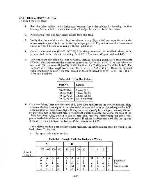
If the M9016 module does not have these resistors, the serial number must be wired to the<br />
back plane. To do this:<br />
a. Set up a table similar to this:<br />
Table 4-4 Sample Table for Backplane Wiring<br />
A B C<br />
800 400 200 100 80 40 20 10 8 4 2 1<br />
A A A A A B A B B B A A<br />
0 1 1 I 1 1 1 1 1 1 1 1 Backplane<br />
6 4 4 4 4 4 4 4 4 4 4 4 Pin<br />
R p R S S M T D C A V V Assignments<br />
2 1 1 2 1 2 2 1 1 1 1 2<br />
4-10


