RK06/RK07 Disk Drive User's Manual - Trailing-Edge
RK06/RK07 Disk Drive User's Manual - Trailing-Edge
RK06/RK07 Disk Drive User's Manual - Trailing-Edge
You also want an ePaper? Increase the reach of your titles
YUMPU automatically turns print PDFs into web optimized ePapers that Google loves.
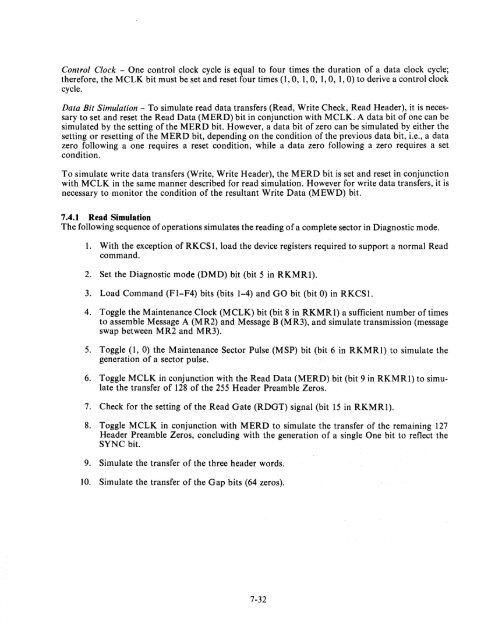
Control Clock - One control clock cycle is equal to four times the duration of a data clock cycle;<br />
therefore, the MCLK bit must be set and reset four times (1,0, 1,0, 1,0, 1,0) to derive a control clock<br />
cycle.<br />
Data Bit Simulation - To simulate read data transfers (Read, Write Check, Read Header), it is necessary<br />
to set and reset the Read Data (MERD) bit in conjunction with MCLK. A data bit of one can be<br />
simulated by the setting of the MERD bit. However, a data bit of zero can be simulated by either the<br />
setting or resetting of the MERD bit, depending on the condition of the previous data bit, i.e., a data<br />
zero following a one requires a reset condition, while a data zero following a zero requires a set<br />
condition.<br />
To simulate write data transfers (Write, Write Header), the MERD bit is set and reset in conjunction<br />
with MCLK in the same manner described for read simulation. However for write data transfers, it is<br />
necessary to monitor the condition of the resultant Write Data (MEWD) bit.<br />
7.4.1 Read Simulation<br />
The following sequence of operations simulates the reading of a complete sector in Diagnostic mode.<br />
1. With the exception of RKCSl, load the device registers required to support a normal Read<br />
command.<br />
2. Set the Diagnostic mode (DMD) bit (bit 5 in RKMRl).<br />
3. Load Command (FI-F4) bits (bits 1-4) and GO bit (bit 0) in RKCSI.<br />
4. Toggle the Maintenance Clock (MCLK) bit (bit 8 in RKMRl) a sufficient number of times<br />
to assemble Message A (MR2) and Message B (MR3), and simulate transmission (message<br />
swap between MR2 and MR3).<br />
5. Toggle (1, 0) the Maintenance Sector Pulse (MSP) bit (bit 6 in RKMRl) to simulate the<br />
generation of a sector pulse.<br />
6. Toggle MCLK in conjunction with the Read Data (MERD) bit (bit 9 in RKMRl) to simulate<br />
the transfer of 128 of the 255 Header Preamble Zeros.<br />
7. Check for the setting of the Read Gate (RDGT) signal (bit 15 in RKMRl).<br />
8. Toggle MCLK in conjunction with MERD to simulate the transfer of the remaining 127<br />
Header Preamble Zeros, concluding with the generation of a single One bit to reflect the<br />
SYNC bit.<br />
9. Simulate the transfer of the three header words.<br />
10. Simulate the transfer of the Gap bits (64 zeros).<br />
7-32


