

RK06/RK07 Disk Drive User's Manual - Trailing-Edge
RK06/RK07 Disk Drive User's Manual - Trailing-Edge
RK06/RK07 Disk Drive User's Manual - Trailing-Edge

You also want an ePaper? Increase the reach of your titles
YUMPU automatically turns print PDFs into web optimized ePapers that Google loves.
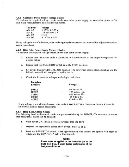
4.4.1 Controller Power Supply Voltage Checks<br />
To perform the required voltage checks on the controller power supply, set controller power to ON<br />
and make measurements at the following points:<br />
Test Point<br />
A04A2<br />
A04B2<br />
A04C2<br />
A04D2<br />
Voltage<br />
+5 Vdc ± 0.25 V<br />
-15 Vdc ± 0.75 V<br />
GND<br />
+15Vdc±0.75<br />
If any voltage is out of tolerance, refer to the appropriate expander box manual for adjustment and/or<br />
repair procedures.<br />
4.4.2 <strong>Disk</strong> <strong>Drive</strong> Power Supply V oltage Checks<br />
To perform the required voltage checks on the disk drive power supply:<br />
1. Ensure that the power cable is connected to a power outlet of the proper voltage and frequency<br />
rating.<br />
2. Ensure that the RUN/STOP switch is in the STOP position.<br />
3. Set circuit breaker CB 1 to the ON position. The air system should start operating and the<br />
lid-lock solenoid will energize to enable the lid.<br />
4. Check the five output voltages at the logic backplane:<br />
Backplane<br />
Location<br />
B08A2<br />
DOIE2<br />
C08D2<br />
C08B2<br />
A08R2<br />
Voltage<br />
+5Vdc±3%<br />
+25 Vdc ± 10%<br />
+15Vdc±5%<br />
-15 Vdc ± 5%<br />
-5Vdc±3%<br />
If any voltage is not within tolerance, refer to the <strong>RK06</strong>/ <strong>RK07</strong> <strong>Disk</strong> Subsystem Service <strong>Manual</strong> for<br />
adjustment and/or repair procedures.<br />
4.4.3 Head Load/Unload Checks<br />
The following head load/unload checks are performed during the POWER ON sequence to ensure<br />
that operational status can be attained:<br />
1. With power ON, install a scratch cartridge into the drive.<br />
2. Depress the appropriate access select switch, either A or B.<br />
3. Press the R UN/STOP switch. After approximately one second, the spindle will begin to<br />
rotate and the R UN/STOP light will extinguish.<br />
NOTE<br />
Power must be applied to the controller (or to the<br />
Field Test Box, if used) during performance of the<br />
load/unload checks.<br />
4-16


