RK06/RK07 Disk Drive User's Manual - Trailing-Edge
RK06/RK07 Disk Drive User's Manual - Trailing-Edge
RK06/RK07 Disk Drive User's Manual - Trailing-Edge
You also want an ePaper? Increase the reach of your titles
YUMPU automatically turns print PDFs into web optimized ePapers that Google loves.
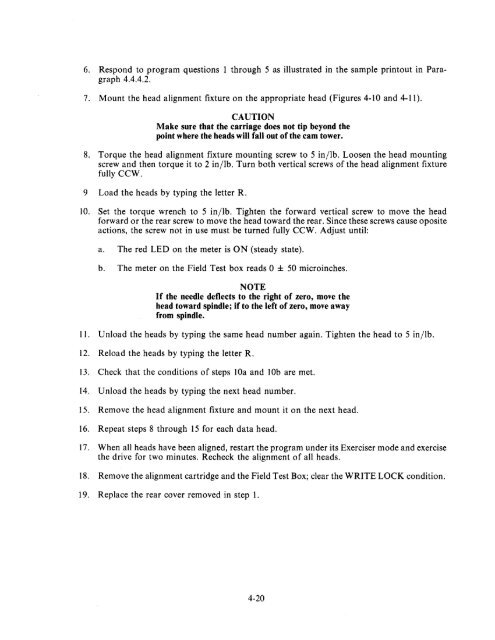
6. Respond to program questions 1 through 5 as illustrated in the sample printout in Paragraph<br />
4.4.4.2.<br />
7. Mount the head alignment fixture on the appropriate head (Figures 4-10 and 4-11).<br />
CAUTION<br />
Make sure that the carriage does not tip beyond the<br />
point where the heads will fall out of the cam tower.<br />
8. Torque the head alignment fixture mounting screw to 5 in/lb. Loosen the head mounting<br />
screw and then torque it to 2 in/lb. Turn both vertical screws of the head alignment fixture<br />
fully CCW.<br />
9 Load the heads by typing the letter R.<br />
10. Set the torque wrench to 5 in/lb. Tighten the forward vertical screw to move the head<br />
forward or the rear screw to move the head toward the rear. Since these screws cause oposite<br />
actions, the screw not in use must be turned fully CCW. Adjust until:<br />
a. The red LED on the meter is ON (steady state).<br />
b. The meter on the Field Test box reads 0 ± 50 microinches.<br />
NOTE<br />
If the needle deflects to the right of zero, move the<br />
head toward spindle; if to the left of zero, move away<br />
from spindle.<br />
11. Unload the heads by typing the same head number again. Tighten the head to 5 in/lb.<br />
12. Reload the heads by typing the letter R.<br />
13. Check that the conditions of steps lOa and lOb are met.<br />
14. Unload the heads by typing the next head number.<br />
15. Remove the head alignment fixture and mount it on the next head.<br />
16. Repeat steps 8 through 15 for each data head.<br />
17. When all heads have been aligned, restart the program under its Exerciser mode and exercise<br />
the drive for two minutes. Recheck the alignment of all heads.<br />
18. Remove the alignment cartridge and the Field Test Box; clear the WRITE LOCK condition.<br />
19. Replace the rear cover removed in step 1.<br />
4-20


