RK06/RK07 Disk Drive User's Manual - Trailing-Edge
RK06/RK07 Disk Drive User's Manual - Trailing-Edge
RK06/RK07 Disk Drive User's Manual - Trailing-Edge
You also want an ePaper? Increase the reach of your titles
YUMPU automatically turns print PDFs into web optimized ePapers that Google loves.
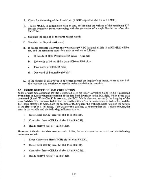
7. Check for the setting of the Read Gate (RDGT) signal bit (bit 15 in RKMRl).<br />
S. Toggle MCLK in conjunction with MERD to simulate the writing of the remaining 127<br />
Header Preamble Zeros, concluding with the generation of a single One bit to reflect the<br />
SYNC bit.<br />
9. Simulate the reading of the three header words.<br />
10. Simulate the Gap bits (64 zeros).<br />
11. If header compare is correct, the Write Gate (WRTGT) signal bit (bit 14 in RKMRl) will be<br />
set, and the remaining sector bits may be written as follows:<br />
a. 16 words of Data Preamble (255 zeros, lOne bit)<br />
b. 256 words of 16- or IS-bit data (4096 or 460S bits)<br />
c. Two words of ECC (32 bits)<br />
d. One word of Postamble (16 bits)<br />
12. If the number of data words to be written exceeds the length of one sector, return to step 5 of<br />
the sequence and continue; otherwise, write simulation is complete.<br />
7.5 ERROR DETECTION AND CORRECTION<br />
When a write data command (Write) is executed, a 32-bit Error Correction Code (ECC) is generated<br />
by the data and, following the recording of the data field, is written in the ECC field. When a read data<br />
command (Read, Write Check) is executed, the ECC field is also read to verify the integrity of the<br />
recorded data. If a read error is detected, the read function of the current command is disabled, and the<br />
ECC logic attempts to define both the position of the first error bit within the data field and the pattern<br />
of the error over an II-bit range. If the data error is confined to no more than an II-bit error burst, the<br />
error is correctable and the following indicators are set:<br />
1. Data Check (DCK) error bit (bit 15 in RKER).<br />
2. Controller Error (CERR) bit (bit 15 in RKCSl).<br />
3. Ready (RDY) bit (bit 7 in RKCS 1).<br />
However, if the detected data error exceeds 11 bits, the error cannot be corrected and the following<br />
indicators are set:<br />
1. Error Correction Hard (ECH) bit (bit 6 in RKER).<br />
2. Data Check (DCK) error bit (bit 15 in RKER).<br />
3. Controller Error (CERR) bit (bit 15 in RKCS 1).<br />
4. Ready (RDY) bit (bit 7 in RKCS 1).<br />
7-34


