RK06/RK07 Disk Drive User's Manual - Trailing-Edge
RK06/RK07 Disk Drive User's Manual - Trailing-Edge
RK06/RK07 Disk Drive User's Manual - Trailing-Edge
You also want an ePaper? Increase the reach of your titles
YUMPU automatically turns print PDFs into web optimized ePapers that Google loves.
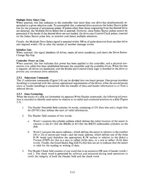
Multiple <strong>Drive</strong> Select Line<br />
When asserted, this line indicates to the controller that more than one drive has simultaneously responded<br />
to a given selection code. To accomplish this, a selected drive monitors the Index/Sector pulse<br />
line for the presence of extraneous pulses. If pulses other than those originating from the desired drive<br />
are detected, the Multiple <strong>Drive</strong> Select line is asserted. However, since Index/Sector pulses cannot be<br />
generated if the heads of the desired drive are not loaded, the drive uses Control Clock pulses, inserted<br />
on the Index/Sector pulse line, to monitor and detect multiple selections.<br />
Finally, the Multiple <strong>Drive</strong> Select signal is asserted within 300 ns of pulse detection from another drive<br />
and negated within 120 ns after the receipt of another message strobe.<br />
Initialize Line<br />
When asserted, this signal deselects all drives, resets all error conditons, and clears the <strong>Drive</strong> Status<br />
Change flip-flop.<br />
Controller Power on Line<br />
When asserted, this line indicates that power has been applied to the controller, and a physical connection<br />
(via cable) has been established between the controller and the available drives. When the line<br />
is negated, all drives are deselected, and the Strobe and Control Clock logic is disabled in the drive to<br />
prevent any erroneous drive selection.<br />
2.5.2 Subsystem Commands<br />
The 13 subsystem commands (Figure 2-4) can be divided into two basic groups. One group (nondata<br />
handling) is concerned with the various operational requirements of the drives, while the second group<br />
(data or header handling) is concerned with the transfer of data and header information to or from a<br />
selected device.<br />
2.5.3 Data Formatting<br />
When the tracks of a disk are formatted via separate Write Header commands, the following information<br />
is recorded to identify each sector in relation to its radial and rotational position on a disk (Figure<br />
2-3).<br />
1. The Header Preamble field contains 16 words, consisting of 255 Zero bits and a single One<br />
bit (SYNC) that defines the start of valid information.<br />
2. The Header field consists of two words:<br />
a. Word 1 contains the cylinder address which defines the radial location of the sector in<br />
relation to the 411 (for the <strong>RK06</strong>) or 815 (for the <strong>RK07</strong>) addressable cylinders on the<br />
disk.<br />
b. Word 2 contains the sector address-which defines the sector in relation to the number<br />
(20 or 22) of sectors per track-and the track address, which defines one of the three<br />
R/W heads (and therefore the appropriate R/W surface in relation to the disks) a<br />
Format (FMT) bit that is a zero to reflect 16-bit data, or a one to reflect 18-bit data<br />
words. Finally, the Good Sector flag (GS FLAG) bits are set to indicate that the sector<br />
is valid for the reading or writing of data.<br />
3. The Header Check field consists of one word that is an exclusive-OR sum of header words 1<br />
and 2. The check word is generated by software and extracted during read operations to<br />
verify the integrity of both the Header field and the check word.<br />
2-12


