RK06/RK07 Disk Drive User's Manual - Trailing-Edge
RK06/RK07 Disk Drive User's Manual - Trailing-Edge
RK06/RK07 Disk Drive User's Manual - Trailing-Edge
You also want an ePaper? Increase the reach of your titles
YUMPU automatically turns print PDFs into web optimized ePapers that Google loves.
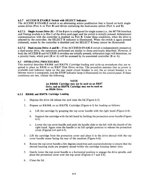
6.2.7 ACCESS B ENABLE Switch with SELECT Indicator<br />
The ACCESS B ENABLE switch is an alternating action pushbutton that is found on both singleaccess<br />
drives (Port A or Port B) and drives containing the dual-access option (Port A and B).<br />
6.2.7.1 Single-Access <strong>Drive</strong> (B) - If the B port is configured for single access (i.e., the M7706 Interface<br />
and Timing module is in Slot 2 of the drive card cage) and the switch is initially pressed, bidirectional<br />
communication with the controller is enabled via Port B. Under these conditions, when the drive is<br />
selected by the controller, the SELECT B indicator is illuminated. When the switch is again pressed<br />
(released), access by the controller is disabled and the SELECT B lamp cannot be illuminated.<br />
6.2.7.2 Dual-Access <strong>Drive</strong> (A and B) - If the ACCESS B ENABLE switch is independently pressed on<br />
a dual-access drive, the operations performed are similar to those previously described. However, if<br />
both the ACCESS B and ACCESS A switches are initially pressed, arbitration logic will determine, on<br />
a priority basis, which port (B or A) will be accessed by its associated controller (B or A).<br />
6.3 OPERATING PROCEDURES<br />
This material describes <strong>RK06</strong>K and <strong>RK07</strong>K Cartridge loading and cycle-up procedures that are required<br />
to place an <strong>RK06</strong> or an <strong>RK07</strong> <strong>Disk</strong> <strong>Drive</strong> on-line. The procedure assumes that ac power is<br />
available (red indicator lamp on the rear panel circuit breaker is on), the ac circuit breaker is on<br />
(blower motor is energized), and the STOP indicator lamp is illuminated on the control panel. If these<br />
conditions are met, initiate the following.<br />
6.3.1 <strong>RK06</strong>K and <strong>RK07</strong>K Cartridge Loading<br />
NOTE<br />
An <strong>RK06</strong>K Cartridge may not be used on an <strong>RK07</strong><br />
<strong>Drive</strong>, and an <strong>RK07</strong>K Cartridge may not be used on<br />
an <strong>RK06</strong> <strong>Drive</strong>.<br />
1. Depress the drive lid release bar and raise the lid (Figure 6-2).<br />
2. Prepare an <strong>RK06</strong>K or an <strong>RK07</strong>K Cartridge (Figure 6-3) for loading as follows:<br />
a. Lift the cartridge by grasping the top cover handle with the right hand (Figure 6-4).<br />
b. Support the cartridge with the left hand by holding the protection cover handle (Figure<br />
6-5).<br />
c. Lower the top cover handle and push the handle slide to the left with the thumb of the<br />
right hand. Again raise the handle to its full upright position to release the protection<br />
cover (Figures 6-4 and 6-5).<br />
3. Lift the cartridge from the protection cover and place it in the drive shroud with the top<br />
cover handle recess facing the rear of the machine (Figure 6-6).<br />
4. Rotate the top cover handle a few degrees clockwise and counterclockwise to ensure that the<br />
shroud locating studs are properly seated within the cartridge housing detent slots.<br />
5. Gently lower the top cover handle to a horizontal position to engage the drive spindle, and<br />
place the protection cover over the top cover (Figures 6-7 and 6-8).<br />
6. Close the lid.<br />
6-4


