

RK06/RK07 Disk Drive User's Manual - Trailing-Edge
RK06/RK07 Disk Drive User's Manual - Trailing-Edge
RK06/RK07 Disk Drive User's Manual - Trailing-Edge

You also want an ePaper? Increase the reach of your titles
YUMPU automatically turns print PDFs into web optimized ePapers that Google loves.
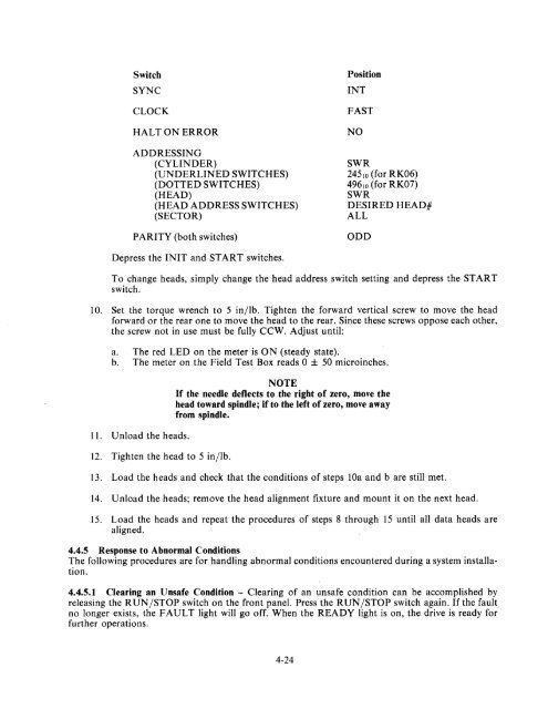
Switch<br />
SYNC<br />
CLOCK<br />
HALTON ERROR<br />
ADDRESSING<br />
(CYLINDER)<br />
(UNDERLINED SWITCHES)<br />
(DOTTED SWITCHES)<br />
(HEAD)<br />
(HEAD ADDRESS SWITCHES)<br />
(SECTOR)<br />
PARITY (both switches)<br />
Depress the INIT and START switches.<br />
Position<br />
INT<br />
FAST<br />
NO<br />
SWR<br />
245,0 (for <strong>RK06</strong>)<br />
496,0 (for <strong>RK07</strong>)<br />
SWR<br />
DESIRED HEAD#<br />
ALL<br />
ODD<br />
To change heads, simply change the head address switch setting and depress the START<br />
switch.<br />
10. Set the torque wrench to 5 in/lb. Tighten the forward vertical screw to move the head<br />
forward or the rear one to move the head to the rear. Since these screws oppose each other,<br />
the screw not in use must be fully CCW. Adjust until:<br />
a. The red LED on the meter is ON (steady state).<br />
b. The meter on the Field Test Box reads 0 ± 50 microinches.<br />
11. Unload the heads.<br />
12. Tighten the head to 5 in/lb.<br />
NOTE<br />
If the needle deflects to the right of zero, move the<br />
head toward spindle; if to the left of zero, move away<br />
from spindle.<br />
13. Load the heads and check that the conditions of steps lOa and b are still met.<br />
14. Unload the heads; remove the head alignment fixture and mount it on the next head.<br />
15. Load the heads and repeat the procedures of steps 8 through 15 until all data heads are<br />
aligned.<br />
4.4.5 Response to Abnormal Conditions<br />
The following procedures are for handling abnormal conditions encountered during a system installation.<br />
4.4.5.1 Clearing an Unsafe Condition - Clearing of an unsafe condition can be accomplished by<br />
releasing the RUN/STOP switch on the front panel. Press the RUN/STOP switch again. If the fault<br />
no longer exists, the FAULT light will go off. When the READY light is on, the drive is ready for<br />
further operations.<br />
4-24


