- Page 1:
CRANFIELD UNIVERSITY MAHADI ABD MUR
- Page 4 and 5:
ABSTRACT One of the most common pro
- Page 7 and 8:
TABLE OF CONTENTS ABSTRACT ........
- Page 9 and 10:
3.7.1 Introduction ................
- Page 11:
5.6 Summary and Conclusions .......
- Page 14 and 15:
Figure 3.1: Schematic diagram of th
- Page 16 and 17:
Figure 5.4: The average temperature
- Page 18 and 19:
NOMENCLATURES ACFM Alternating Curr
- Page 21 and 22:
1 INTRODUCTION One of the most comm
- Page 23 and 24:
1.1 Objectives Knowing this backgro
- Page 25 and 26:
The methodology of this integrated
- Page 27 and 28:
Chapter 6 contains the summary and
- Page 29 and 30:
period of the major part of the exi
- Page 31 and 32:
Figure 2.2: Reported interest in de
- Page 33 and 34:
Figure 2.4: Dent damage caused by v
- Page 35 and 36:
presented current practices, recent
- Page 37 and 38:
Energy Workforce Sdn Bhd (2011) cla
- Page 39 and 40:
available provides real time detect
- Page 41 and 42:
2.3.3 Reliability Analysis of Infor
- Page 43 and 44:
Figure 2.9: Pipeline failure probab
- Page 45 and 46:
2.3.3.1 NDT Reliability and POD cur
- Page 47 and 48:
increase in the yield limit of stee
- Page 49 and 50:
the SCC assessment in their integri
- Page 51 and 52:
Manufacturers such as Walkers Techn
- Page 53 and 54:
Company L.P, 2005); Aquawrap ® pro
- Page 55 and 56:
monitoring, inspection, and damage
- Page 57 and 58:
2.6.2 Aims of Structural Health Mon
- Page 59 and 60:
Figure 2.16: Application fields and
- Page 61 and 62:
egistered by the piezoelectric sens
- Page 63 and 64:
discretization error. Round-off err
- Page 65 and 66:
notches and Neuber‘s is better fo
- Page 67 and 68:
maximum local stress at discontinui
- Page 69 and 70:
De Carvalho (2005) concludes that t
- Page 71 and 72:
accurate simulation of loading espe
- Page 73 and 74:
Based on the above facts, the opera
- Page 75 and 76:
3 FINITE ELEMENT ANALYSIS (FEA) IN
- Page 77 and 78:
Figure 3.2: Schematic diagram of th
- Page 79 and 80:
In this modelling work (i.e. compos
- Page 81 and 82:
This partition toolset also helps u
- Page 83 and 84:
Figure 3.6: Mesh control using Swee
- Page 85 and 86:
Figure 3.7: Schematic representatio
- Page 87 and 88:
discretization. Therefore, in this
- Page 89 and 90:
According to Staten et al. (2010b),
- Page 91 and 92:
3.5 The influence of pressure on th
- Page 93 and 94:
each pressure value remains constan
- Page 95 and 96:
Axial Stress, σa (S22) was referre
- Page 97 and 98:
Figure 3.14 shows a graph of analyt
- Page 99 and 100:
the notch defect is found to be in
- Page 101 and 102:
One of the contributions of this st
- Page 103 and 104:
Table 3.4: Convergence tests on var
- Page 105 and 106:
Figures 3.16 and 3.17 show that the
- Page 107 and 108:
Figure 3.20 shows that as the relat
- Page 109 and 110:
3.7.4 Concluding Remarks A biaxial
- Page 111 and 112:
yarns change and lateral contact be
- Page 113 and 114:
For predicting E2 and Gl2, a number
- Page 115 and 116:
Where: Ar = weight of one sheet of
- Page 117 and 118:
Where; The Stiffness matrix is trad
- Page 119 and 120:
simulations for the hoop strain at
- Page 121 and 122:
Figure 3.24: Finding the hoop stres
- Page 123 and 124: Table 3.8: The effect of repair len
- Page 125 and 126: four up to 18 layers. In this study
- Page 127 and 128: hoop and axial stress concentration
- Page 129 and 130: Table 3.11: Predicted Elastic Const
- Page 131 and 132: Table 3.13: Axial Stress v/s L/W ra
- Page 133 and 134: Hoop Stress (MPa) Figure 3.3: Hoop
- Page 135 and 136: However, Frost (2008) and Alexander
- Page 137 and 138: Table 3.17: Ratio of Axial Stress N
- Page 139 and 140: axial load (e.g. buried pipelines t
- Page 141 and 142: 3.10 Numerical Strain Analysis of C
- Page 143 and 144: Figure 3.36 shows the contours befo
- Page 145 and 146: Stress Concentration Factor 2 1.8 1
- Page 147 and 148: In fact, for Notch 40 with 18 plies
- Page 149 and 150: this second approach (i.e. the expe
- Page 151 and 152: 4.2.2 Strain Gauge Selection and Cr
- Page 153 and 154: Finally, a method used to calculate
- Page 155 and 156: Where, and are the maximum and mini
- Page 157 and 158: should be between 20 and 28 bar and
- Page 159 and 160: welded weld neck flange at both end
- Page 161 and 162: Figure 4.7: Sensor and heating elem
- Page 163 and 164: Figure 4.9: A summary of data acqui
- Page 165 and 166: One of the objectives of doing this
- Page 167 and 168: Figure 4.14: A schematic diagram of
- Page 169 and 170: Table 4.1: Strain gauge readings at
- Page 171 and 172: microstrain 3.00E-04 2.50E-04 2.00E
- Page 173: However, the axial load transfer is
- Page 177 and 178: Since the defect is not a flat notc
- Page 179 and 180: Again, the epoxy resin plays a sign
- Page 181 and 182: Table 4.4: Study at the defect area
- Page 183 and 184: Mircostrain 300 250 200 150 100 50
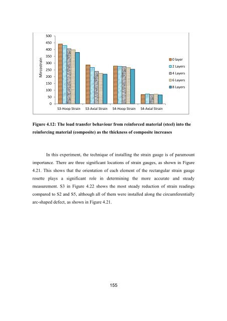
- Page 185 and 186: Mircostrain 600 500 400 300 200 100
- Page 187 and 188: 14.25% in hoop strain and 23.5% in
- Page 189 and 190: consideration for the selection of
- Page 191 and 192: 5.4 Methodology of Thermal Expansio
- Page 193 and 194: Figure 5.1: Some preventive measure
- Page 195 and 196: 5.4.1 The Fundamentals of the Therm
- Page 197 and 198: 5.5 Analysis of Results 5.5.1 The t
- Page 199 and 200: Thermal Output (strain ) 0.0002 0.0
- Page 201 and 202: (Strain ,ε) Figure 5.12: Coefficie
- Page 203 and 204: (Strain ,ε) 0.0002 0.00018 0.00016
- Page 205 and 206: Table 5.1: The strain readings afte
- Page 207 and 208: maximum shear strain increase as th
- Page 209 and 210: The above results show that shear s
- Page 211 and 212: shear strains becomes more stable a
- Page 213 and 214: for future safe design and operatio
- Page 215 and 216: has been fully cured. Poor surface
- Page 217 and 218: 6.3 Primary PhD Achievements The ea
- Page 219 and 220: In Chapter 5, the CTE was determine
- Page 221 and 222: ASM International (2002), "Thermal
- Page 223 and 224: Bucinell, R. B. (2001), Calculating
- Page 225 and 226:
Proceedings of OMAE'01 20th Interna
- Page 227 and 228:
Greenwood, R. (2002), UKOPA Pipelin
- Page 229 and 230:
Kotrechko, S. A., Krasovskii, A. Y.
- Page 231 and 232:
Mousavi, S. E., Xiao, H. and Sukuma
- Page 233 and 234:
Raju, I. S. and Newman, J. C. (1986
- Page 235 and 236:
Tennyson, R. C. and Mufti, A. A. (2
- Page 237 and 238:
Xue, L., Widera, G. E. O. and Sang,
- Page 239 and 240:
General Technical Specifications: T
- Page 241 and 242:
Photos of the Design and Build of t
- Page 243 and 244:
Composite Installation Process usin
- Page 245 and 246:
APPENDIX 3 - STRAIN GAUGE INSTALLAT
- Page 247 and 248:
Figure 7: Mylar tape was stuck onto
- Page 249 and 250:
Figure 19: Repeating the above proc
- Page 251:
2) Electrical Insulation Test Resul