Single-Chip Low Power RF Transceiver for Narrowband Systems ...
Single-Chip Low Power RF Transceiver for Narrowband Systems ...
Single-Chip Low Power RF Transceiver for Narrowband Systems ...

Create successful ePaper yourself
Turn your PDF publications into a flip-book with our unique Google optimized e-Paper software.
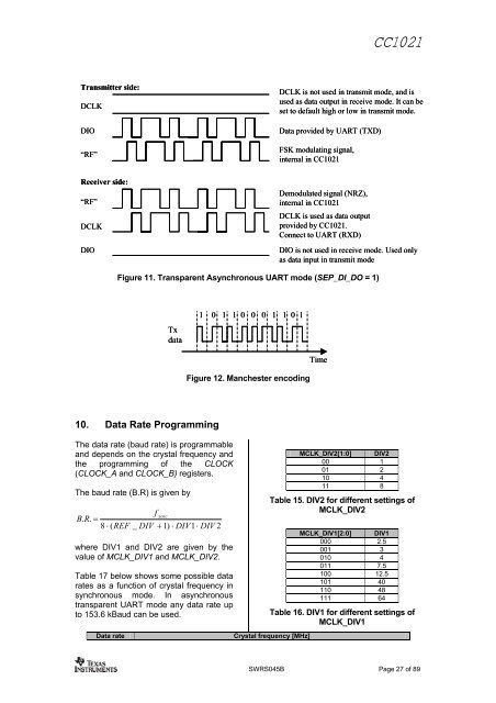
Transmitter side:<br />
DCLK<br />
DIO<br />
“<strong>RF</strong>”<br />
Receiver side:<br />
“<strong>RF</strong>”<br />
DCLK<br />
DIO<br />
CC1021<br />
DCLK is not used in transmit mode, and is<br />
used as data output in receive mode. It can be<br />
set to default high or low in transmit mode.<br />
Data p rovided by UART (TX D)<br />
FSK modulating signal,<br />
internal in CC 102 1<br />
Demodulated signal (NRZ),<br />
intern al in CC1021<br />
DCLK is use d as data output<br />
provided by CC10 21.<br />
Connect to UART (RXD)<br />
DIO is not u sed in receive mo de. U sed only<br />
as data inpu t in tra nsmit mode<br />
Figure 11. Transparent Asynchronous<br />
UART mode<br />
(SEP_DI_DO = 1)<br />
Tx<br />
data<br />
10. Dat a Rate Programming The da ta rate (baud rate) is programmable and depend s on the crystal frequency and<br />
the progra mming of the CLOCK<br />
(CLOCK_A and CLOCK_B) registers. The baud rate (B.R) is given by<br />
f xosc<br />
B.<br />
R.<br />
=<br />
8 ⋅ (REF<br />
_ DIV + 1)<br />
⋅ DIV1⋅<br />
DIV 2<br />
where D IV1 and DIV2 are given by the<br />
value of MCL K_DIV1 and<br />
MCLK_DIV2.<br />
Table 17 belo w shows some possible data<br />
rates as a function<br />
of crystal frequency in<br />
synchronous mode. In asynchronous<br />
transparent<br />
UART mode any data rate up<br />
to 153.6 kBaud can be used.<br />
1 0 1 1 0 0 0 1 1 0 1<br />
Figure 12. Manchester encoding<br />
Data rate Crystal frequency [MHz]<br />
Time<br />
MCLK_DIV2[1: 0] DIV2<br />
00 1<br />
01 2<br />
10 4<br />
11 8<br />
Table 15. DIV2 <strong>for</strong> different settings of<br />
MCLK_DIV2<br />
MCLK_DIV1[2:0] DIV1<br />
000 2.5<br />
001 3<br />
010 4<br />
011 7.5<br />
100 12.5<br />
101 40<br />
110 48<br />
111 64<br />
Table 16. DIV1 <strong>for</strong> different settings of<br />
MCLK_DIV1<br />
SWRS045B Page 27 of 89