

Single-Chip Low Power RF Transceiver for Narrowband Systems ...
Single-Chip Low Power RF Transceiver for Narrowband Systems ...
Single-Chip Low Power RF Transceiver for Narrowband Systems ...

Create successful ePaper yourself
Turn your PDF publications into a flip-book with our unique Google optimized e-Paper software.
15.2. VCO and PLL Self-Calibration<br />
To compensate <strong>for</strong> supply voltage,<br />
temperature and process variations, the<br />
VCO and PLL must be calibrated. The<br />
calibration is per<strong>for</strong>med automatically and<br />
sets the maximum VCO tuning range and<br />
optimum charge pump current <strong>for</strong> PLL<br />
stability. After setting up the device at the<br />
operating frequency, the self-calibration<br />
can be initiated by setting the<br />
CAL_START bit in the CALIBRATE<br />
register. The calibration result is stored<br />
internally in the chip, and is valid as long<br />
as power is not turned off. If large supply<br />
voltage drops (typically more than 0.25 V)<br />
or temperature variations (typically more<br />
than 40 o C) occur after calibration, a new<br />
calibration should be per<strong>for</strong>med.<br />
The nominal VCO<br />
control voltage is set by<br />
the<br />
CAL_ITERATE[2:0] bits in the<br />
CALIBRATE register.<br />
The CAL_COMPLETE bit in the STATUS<br />
register indicates that calibration has<br />
finished.<br />
The calibration wait time<br />
(CAL_WAIT) is programmable and is<br />
proportional to the internal PLL reference<br />
frequency.<br />
The highest possible reference<br />
frequency should be used to get the<br />
minimum calibration time. It is<br />
recommended<br />
to use CAL_WAIT[1:0] = 11<br />
in order to get the most accurate loop<br />
bandwidth.<br />
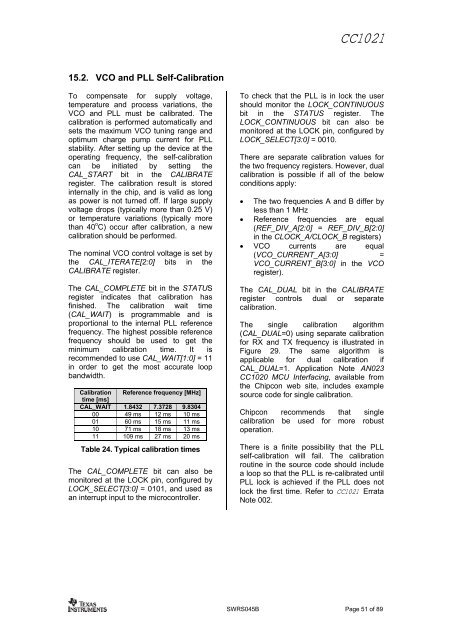
Calibration<br />
time [ms]<br />
Reference frequency [MHz]<br />
CAL_WAIT 1.8432 7.3728 9.8304<br />
00 49 ms 12 ms 10 ms<br />
01 60 ms 15 ms 11 ms<br />
10 71 ms 18 ms 13 ms<br />
11 109 ms 27 ms 20 ms<br />
Table 24. Typical calibration times<br />
The CAL_COMPLETE bit can also be<br />
monitored at the LOCK pin, configured<br />
by<br />
LOCK_SELECT[3:0]<br />
= 0101, and used as<br />
an<br />
interrupt input to the microcontroller.<br />
CC1021<br />
To check that the PLL is in lock the user<br />
should monitor the LOCK_CONTINUOUS<br />
bit in the STATUS register. The<br />
LOCK_CONTINUOUS bit can also be<br />
monitored<br />
at the LOCK pin, configured by<br />
LOCK_SELECT[3:0]<br />
= 0010.<br />
There are separate calibration values <strong>for</strong><br />
the two frequency registers. However, dual<br />
calibration is possible if all of the below<br />
conditions apply:<br />
• The two frequencies<br />
A and B differ by<br />
less than 1 MHz<br />
• Reference<br />
frequencies are equal<br />
(REF_DIV_A[2:0] = REF_DIV_B[2:0]<br />
in the CLOCK_A/CLOCK_B<br />
registers)<br />
• VCO currents are equal<br />
(VCO_CURRENT_A[3:0]<br />
=<br />
VCO_CURRENT_B[3:0] in the VCO<br />
register).<br />
The CAL_DUAL bit in the CALIBRATE<br />
register controls dual or separate<br />
calibration.<br />
The single calibration<br />
algorithm<br />
(CAL_DUAL=0) using separate calibration<br />
<strong>for</strong><br />
RX and TX frequency is illustrated in<br />
Figure 29. The same algorithm<br />
is<br />
applicable <strong>for</strong> dual calibration if<br />
CAL_DUAL=1. Application<br />
Note AN023<br />
CC1020<br />
MCU Interfacing, available from<br />
the <strong>Chip</strong>con web site, includes example<br />
source code <strong>for</strong> single<br />
calibration.<br />
<strong>Chip</strong>con recommends that<br />
single<br />
calibration be used<br />
<strong>for</strong> more robust<br />
operation.<br />
There is a finite possibility that the PLL<br />
self-calibration will fail. The calibration<br />
routine in the source code should include<br />
a loop so that<br />
the PLL is re-calibrated until<br />
PLL lock is achieved<br />
if the PLL does not<br />
lock the first time. Refer to CC1021 Errata<br />
Note 002.<br />
SWRS045B Page 51 of 89


