- Page 1 and 2:
Dell PowerEdge Configuration Guide
- Page 3 and 4:
October 2012 | iii
- Page 5 and 6:
1 About this Guide . . . . . . . .
- Page 7 and 8:
Data Center Bridging Exchange Proto
- Page 9 and 10:
Displaying VLAN Membership . . . .
- Page 11 and 12:
Read Managed Object Values . . . .
- Page 13 and 14:
Troubleshooting Packet Loss . . . .
- Page 15 and 16:
About this Guide Objectives 1 This
- Page 17 and 18:
Before You Start Default Settings 2
- Page 19 and 20:
DCB Support DCB enhancements for da
- Page 21 and 22:
The untagged VLAN of a server-facin
- Page 23 and 24:
Configuration Fundamentals 3 The De
- Page 25 and 26:
Navigating CLI Modes The FTOS promp
- Page 27 and 28:
Figure 3-5. Undoing a command with
- Page 29 and 30:
Table 3-2. Short-Cut Keys and their
- Page 31 and 32:
Multiple Users in Configuration Mod
- Page 33 and 34:
Getting Started This chapter contai
- Page 35 and 36:
Uplink Ports Ports 33 to 56 are ext
- Page 37 and 38:
Step Task (continued) Note: Termina
- Page 39 and 40:
Figure 4-4. Completed Boot Process
- Page 41 and 42:
Figure 4-6. Completed Boot Process
- Page 43 and 44:
Access the Aggregator Remotely Conf
- Page 45 and 46:
Dell Force10 recommends using the e
- Page 47 and 48:
Figure 4-10 shows an example of usi
- Page 49 and 50:
To view the contents of a file, fol
- Page 51 and 52:
Figure 4-14. Alternative Storage Lo
- Page 53 and 54:
Aggregator Management This chapter
- Page 55 and 56:
Changing System Logging Settings Yo
- Page 57 and 58:
Configuring a UNIX Logging Facility
- Page 59 and 60:
Enabling the FTP Server To enable t
- Page 61 and 62:
Recovering from a Forgotten Passwor
- Page 63 and 64:
Figure 5-5. Recovering from a Faile
- Page 65 and 66:
Data Center Bridging (DCB) 6 On an
- Page 67 and 68:
Figure 6-1. Priority-Based Flow Con
- Page 69 and 70:
Data Center Bridging Exchange Proto
- Page 71 and 72:
QoS dot1p Traffic Classification an
- Page 73 and 74:
How Enhanced Transmission Selection
- Page 75 and 76:
DCB Policies in a Switch Stack A DC
- Page 77 and 78:
Note: On a DCBX port, application p
- Page 79 and 80:
Auto-Detection of the DCBX Version
- Page 81 and 82:
DCBX Error Messages An error in DCB
- Page 83 and 84:
Figure 6-7. show interfaces pfc sum
- Page 85 and 86:
Table 6-3. show interface pfc summa
- Page 87 and 88:
Table 6-4. show interface ets detai
- Page 89 and 90:
Figure 6-12. show interface dcbx de
- Page 91 and 92:
Example: PFC and ETS Operation This
- Page 93 and 94:
Table 6-8. Example: priority group-
- Page 95 and 96:
Skippy812 Dynamic Host Configuratio
- Page 97 and 98:
Assigning an IP Address Using DHCP
- Page 99 and 100:
Releasing and Renewing DHCP-based I
- Page 101 and 102:
Figure 7-5. DHCP Client: Debug Mess
- Page 103 and 104:
DHCP Client on a Management Interfa
- Page 105 and 106:
FIP Snooping 8 FIP snooping is auto
- Page 107 and 108:
Figure 8-1. FIP discovery and login
- Page 109 and 110:
The following sections describe how
- Page 111 and 112:
FIP Snooping Prerequisites On an Ag
- Page 113 and 114:
Figure 8-3. show fip-snooping sessi
- Page 115 and 116:
Figure 8-7. show fip-snooping stati
- Page 117 and 118:
Table 8-5. show fip-snooping statis
- Page 119 and 120:
FIP Snooping Example Figure 8-11 sh
- Page 121 and 122:
Internet Group Management Protocol
- Page 123 and 124:
IGMP Version 3 Conceptually, IGMP v
- Page 125 and 126:
Leaving and Staying in Groups Figur
- Page 127 and 128:
Figure 9-6. show ip igmp groups Com
- Page 129 and 130:
Interfaces 10 This chapter describe
- Page 131 and 132:
Viewing Interface Information You c
- Page 133 and 134:
Disabling and Re-enabling a Physica
- Page 135 and 136:
The Aggregator supports the managem
- Page 137 and 138:
Configuring a Static Route for a Ma
- Page 139 and 140:
Port-Based VLANs Port-based VLANs a
- Page 141 and 142:
Displaying VLAN Membership To view
- Page 143 and 144:
Adding an Interface to an Untagged
- Page 145 and 146:
Port channels can contain a mix of
- Page 147 and 148:
Figure 10-12. show interface port-c
- Page 149 and 150:
Create a Multiple-Range Figure 10-1
- Page 151 and 152:
Maintenance Using TDR The time doma
- Page 153 and 154:
MTU Size The Aggregator auto-config
- Page 155 and 156:
Figure 10-19. show interfaces statu
- Page 157 and 158:
Figure 10-21 shows the auto-negotia
- Page 159 and 160:
Clearing Interface Counters The cou
- Page 161 and 162:
iSCSI Optimization 11 An Aggregator
- Page 163 and 164:
If no iSCSI traffic is detected for
- Page 165 and 166:
Displaying iSCSI Optimization Infor
- Page 167 and 168:
Link Aggregation The Aggregator aut
- Page 169 and 170:
LACP Example Figure 12-1 shows an e
- Page 171 and 172:
Figure 12-3. show lacp 128 Command
- Page 173 and 174:
Figure 12-5. show interfaces port-c
- Page 175 and 176:
Layer 2 The Aggregator supports CLI
- Page 177 and 178:
Figure 13-1. Redundant NICs with NI
- Page 179 and 180:
Link Layer Discovery Protocol (LLDP
- Page 181 and 182:
Organizationally Specific TLVs Orga
- Page 183 and 184:
TIA Organizationally Specific TLVs
- Page 185 and 186:
LLDP-MED Network Policies TLV A net
- Page 187 and 188:
LLDP Operation On an Aggregator, LL
- Page 189 and 190:
Figure 14-10. Viewing All Informati
- Page 191 and 192:
Debugging LLDP The debug lldp comma
- Page 193 and 194: Table 14-8. LLDP System MIB Objects
- Page 195 and 196: Table 14-10. LLDP-MED System MIB Ob
- Page 197 and 198: Port Monitoring 15 The Aggregator s
- Page 199 and 200: Figure 15-2 shows ports 0/25 and 0/
- Page 201 and 202: In Figure 15-4, the host and server
- Page 203 and 204: 16 Simple Network Management Protoc
- Page 205 and 206: Dell Force10 supports RFC 4001, Tex
- Page 207 and 208: Figure 16-6 shows the output for an
- Page 209 and 210: Use dot3aCurAggFdbTable to fetch th
- Page 211 and 212: Monitor Port-channels To check the
- Page 213 and 214: The status of the MIBS is as follow
- Page 215 and 216: Stacking Overview 17 An Aggregator
- Page 217 and 218: Stack Master Election The stack ele
- Page 219 and 220: Stacking Port Numbers By default, e
- Page 221 and 222: Cabling Procedure The following cab
- Page 223 and 224: Resetting a Unit on a Stack Use the
- Page 225 and 226: Figure 17-19. show system Command E
- Page 227 and 228: Troubleshooting a Switch Stack Trou
- Page 229 and 230: Figure 17-27. show hardware stack-u
- Page 231 and 232: Stack Unit in Card-Problem State Du
- Page 233 and 234: Upgrading a Single Stack Unit Upgra
- Page 235 and 236: Broadcast Storm Control 18 On the A
- Page 237 and 238: System Time and Date 19 The Aggrega
- Page 239 and 240: Setting the Time Zone Universal tim
- Page 241 and 242: Setting Recurring Daylight Saving T
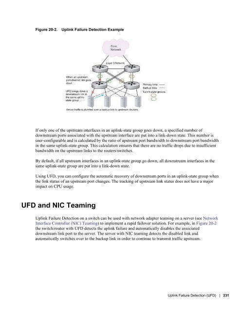
- Page 243: Uplink Failure Detection (UFD) Upli
- Page 247 and 248: Show Command Syntax Description sho
- Page 249 and 250: Debugging UFD on an Interface To en
- Page 251 and 252: Upgrade Procedures 21 To view the r
- Page 253 and 254: Debugging and Diagnostics The chapt
- Page 255 and 256: Broadcast, unknown multicast, and D
- Page 257 and 258: Auto-configured VLANs do not exist
- Page 259 and 260: Figure 22-2. show system stack-unit
- Page 261 and 262: Figure 22-3. Taking a Stack Unit Of
- Page 263 and 264: Table 22-2. show hardware Commands
- Page 265 and 266: Recognize an Over-Temperature Condi
- Page 267 and 268: The simple network management proto
- Page 269 and 270: Deciding to Tune Buffers Dell Force
- Page 271 and 272: Figure 22-11. Displaying Buffer Pro
- Page 273 and 274: Sample Buffer Profile Configuration
- Page 275 and 276: Figure 22-14. Displaying Buffer Sta
- Page 277 and 278: Displaying Stack Port Statistics Th
- Page 279 and 280: Figure 22-19. Mini application core
- Page 281 and 282: Standards Compliance This chapter c
- Page 283 and 284: General IPv4 Protocols RFC# Full Na
- Page 285 and 286: Network Management (continued) RFC#