- Page 1 and 2:
Instruction Manual A533-50-880 Issu
- Page 3 and 4:
A533-50-880 Issue D Setup Password
- Page 5 and 6:
CONTENTS Section Title Page 1 INTRO
- Page 7 and 8:
Section Title Page 3.20.2 Configure
- Page 9 and 10:
Section Title Page 8 SERVICE, SPARE
- Page 11 and 12:
Illustrations (continued) Figure Ti
- Page 13 and 14:
1 INTRODUCTION 1.1 Scope and defini
- Page 15 and 16:
1.2ATEX directive implications •
- Page 17 and 18:
1.4 Safety All of the components of
- Page 19 and 20:
1. Inlet 2. HCMB oil filler-plug *
- Page 21 and 22: 1. Two-way gearbox vent-valve 2. Ge
- Page 23 and 24: 1.10 Electrical system Refer to Fig
- Page 25 and 26: Figure 1-3 - Schematic diagram of t
- Page 27 and 28: iH Dry Pumping Systems 1-15 Figure
- Page 29 and 30: 1. Rear cover 16. Fuse F6 2. Coolin
- Page 31 and 32: Figure 1-6 - Electrical components
- Page 33 and 34: Note that when you first switch-on
- Page 35 and 36: As supplied the first page of Norma
- Page 37 and 38: 1.14 Drip tray The drip tray is fit
- Page 39 and 40: A AW/6179/A 6 2 1 5 4 3 B 9 6 8 4 7
- Page 41 and 42: A. iH80 B. iH600 C. iH1000 1. Warni
- Page 43 and 44: 2TECHNICAL DATA Notes: Unless other
- Page 45 and 46: A B C Side view Plan view Outlet Di
- Page 47 and 48: A Side view 1. Inlet 3. Air-extract
- Page 49 and 50: 2.4 Cooling-water supply Notes. Use
- Page 51 and 52: 1. 60Hz 2. 50Hz Figure 2-6 - Typica
- Page 53 and 54: Note: Discontinuity in curves are a
- Page 55 and 56: Note: Discontinuity in curves are a
- Page 57 and 58: Supply voltage and frequency iH80
- Page 59 and 60: 2.10 Resource conservation Measures
- Page 61 and 62: 2.13 Tracer gas analysis IH600 pump
- Page 63 and 64: 3 INSTALLATION 3.1 Safety WARNING O
- Page 65 and 66: Mounting3.21.2 Electrical Installat
- Page 67 and 68: 1. iH system 2. Nut and washer 3. S
- Page 69 and 70: 3.5 Reconfigure the nitrogen and/or
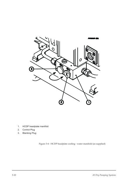
- Page 71: 2. Wheel the iH system on its casto
- Page 75 and 76: Figure 3-5 - System arrangement to
- Page 77 and 78: Use the following procedure to conn
- Page 79 and 80: A B Remove the blanking panel Fit t
- Page 81 and 82: A iH80 1. Inlet spool piece 4. HCMB
- Page 83 and 84: 1. iH80 system 2. Electrics Box 3.
- Page 85 and 86: A B C D iH80 system iH600 system Hi
- Page 87 and 88: A iH80 1. Pin 1 (phase 1) 6. Electr
- Page 89 and 90: Notes: On an iH1000 system, the ear
- Page 91 and 92: 5. Inspect the water hoses, pipelin
- Page 93 and 94: When you switch on an iH600 system,
- Page 95 and 96: 3.21.2 Mounting The disconnect box
- Page 97 and 98: 3.21.5 Cable connections Connect th
- Page 99 and 100: 1. Customer supply: 1.36 inch diame
- Page 101 and 102: 3.22.3 Piping connections Connect t
- Page 103 and 104: 4 PUMP DISPLAY TERMINAL MENUS AND D
- Page 105 and 106: Other specific uses of the CANCEL b
- Page 107 and 108: 8. Press the ENTER button; the disp
- Page 109 and 110: Switch on ▲ SELECT PUMP Process p
- Page 111 and 112: Normal DP DP BODY . kW . C ☞ Firs
- Page 113 and 114: Figure 4-6 - Status menu: sheet 2 o
- Page 115 and 116: Setup SETUP PASSWORD Password ▲
- Page 117 and 118: Next option Prev option [4-8/2] ▲
- Page 119 and 120: Units ▲ ☞ Press the CANCEL butt
- Page 121 and 122: Service SERVICE PASSWORD Password
- Page 123 and 124:
▲ Serial Menu ☞ Use this menu t
- Page 125 and 126:
Notes: You should only use this men
- Page 127 and 128:
Next option Prev option [4-16/1]
- Page 129 and 130:
Last parameter [4-17/2] ▲ View St
- Page 131 and 132:
Messages MESSAGES English ENTER ▲
- Page 133 and 134:
5 OPERATION 5.1 Introduction The fo
- Page 135 and 136:
5.2.3 Gas purges WARNING If you use
- Page 137 and 138:
5.4.2Change the display units If re
- Page 139 and 140:
• The solenoid-valve(s) in the Ga
- Page 141 and 142:
5.10 Manual shut-down WARNING If yo
- Page 143 and 144:
If you need to shut down the iH sys
- Page 145 and 146:
5.14 Restart the iH system after em
- Page 147 and 148:
5.16 Operation of the load-lock pum
- Page 149 and 150:
6 MAINTENANCE 6.1 Safety WARNING Ob
- Page 151 and 152:
1. Tube fitting 2. Front (tapered)
- Page 153 and 154:
6.5 Check the purge gas flow rates
- Page 155 and 156:
1. Exhaust pipe insulation jacket 2
- Page 157 and 158:
6.7 Check the HCMB pump oil-level (
- Page 159 and 160:
3. Refer to Figure 1-1. Check that
- Page 161 and 162:
1. Shut down the iH system (refer t
- Page 163 and 164:
6.15 Relocate the iH system for mai
- Page 165 and 166:
6.17 Fault finding WARNING Only per
- Page 167 and 168:
6.18 Disconnect box and photohelic
- Page 169 and 170:
Warning message Advisory message Me
- Page 171 and 172:
Warning message Advisory message Me
- Page 173 and 174:
Warning message Advisory message Me
- Page 175 and 176:
Alarm message Advisory message Mean
- Page 177 and 178:
Message PUMP STOPPED Press CANCEL E
- Page 179 and 180:
7 STORAGE AND DISPOSAL 7.1 Storage
- Page 181 and 182:
2. If the HCDP pump and HCMB pump (
- Page 183 and 184:
8 SERVICE, SPARES AND ACCESSORIES 8
- Page 185 and 186:
8.4.4 iH Enclosure Extraction Fan K
- Page 187 and 188:
8.5.8 iH Pump Display Module When f
- Page 189 and 190:
Return of BOC Edwards Equipment - P
- Page 191 and 192:
This page intentionally blank.