Edwards iH Dry Pumping Systems, iH80, iH600, iH1000
Edwards iH Dry Pumping Systems, iH80, iH600, iH1000
Edwards iH Dry Pumping Systems, iH80, iH600, iH1000
You also want an ePaper? Increase the reach of your titles
YUMPU automatically turns print PDFs into web optimized ePapers that Google loves.
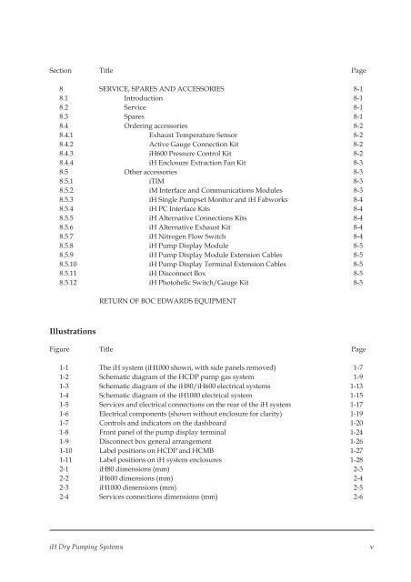
Section Title Page<br />
8 SERVICE, SPARES AND ACCESSORIES 8-1<br />
8.1 Introduction 8-1<br />
8.2 Service 8-1<br />
8.3 Spares 8-1<br />
8.4 Ordering accessories 8-2<br />
8.4.1 Exhaust Temperature Sensor 8-2<br />
8.4.2 Active Gauge Connection Kit 8-2<br />
8.4.3 <strong>iH</strong>600 Pressure Control Kit 8-2<br />
8.4.4 <strong>iH</strong> Enclosure Extraction Fan Kit 8-3<br />
8.5 Other accessories 8-3<br />
8.5.1 iTIM 8-3<br />
8.5.2 iM Interface and Communications Modules 8-3<br />
8.5.3 <strong>iH</strong> Single Pumpset Monitor and <strong>iH</strong> Fabworks 8-4<br />
8.5.4 <strong>iH</strong> PC Interface Kits 8-4<br />
8.5.5 <strong>iH</strong> Alternative Connections Kits 8-4<br />
8.5.6 <strong>iH</strong> Alternative Exhaust Kit 8-4<br />
8.5.7 <strong>iH</strong> Nitrogen Flow Switch 8-4<br />
8.5.8 <strong>iH</strong> Pump Display Module 8-5<br />
8.5.9 <strong>iH</strong> Pump Display Module Extension Cables 8-5<br />
8.5.10 <strong>iH</strong> Pump Display Terminal Extension Cables 8-5<br />
8.5.11 <strong>iH</strong> Disconnect Box 8-5<br />
8.5.12 <strong>iH</strong> Photohelic Switch/Gauge Kit 8-5<br />
RETURN OF BOC EDWARDS EQUIPMENT<br />
Illustrations<br />
Figure Title Page<br />
1-1 The <strong>iH</strong> system (<strong>iH</strong>1000 shown, with side panels removed) 1-7<br />
1-2 Schematic diagram of the HCDP pump gas system 1-9<br />
1-3 Schematic diagram of the <strong>iH</strong>80/<strong>iH</strong>600 electrical systems 1-13<br />
1-4 Schematic diagram of the <strong>iH</strong>1000 electrical system 1-15<br />
1-5 Services and electrical connections on the rear of the <strong>iH</strong> system 1-17<br />
1-6 Electrical components (shown without enclosure for clarity) 1-19<br />
1-7 Controls and indicators on the dashboard 1-20<br />
1-8 Front panel of the pump display terminal 1-24<br />
1-9 Disconnect box general arrangement 1-26<br />
1-10 Label positions on HCDP and HCMB 1-27<br />
1-11 Label positions on <strong>iH</strong> system enclosures 1-28<br />
2-1 <strong>iH</strong>80 dimensions (mm) 2-3<br />
2-2 <strong>iH</strong>600 dimensions (mm) 2-4<br />
2-3 <strong>iH</strong>1000 dimensions (mm) 2-5<br />
2-4 Services connections dimensions (mm) 2-6<br />
<strong>iH</strong> <strong>Dry</strong> <strong>Pumping</strong> <strong>Systems</strong><br />
v


