

Edwards iH Dry Pumping Systems, iH80, iH600, iH1000
Edwards iH Dry Pumping Systems, iH80, iH600, iH1000
Edwards iH Dry Pumping Systems, iH80, iH600, iH1000

Create successful ePaper yourself
Turn your PDF publications into a flip-book with our unique Google optimized e-Paper software.
3.21.5 Cable connections<br />
Connect the cables from the disconnect box to the appropriate locations as follows:<br />
1. Punch out the EMO cable outlet hole (2) on the bottom of the disconnect box. See Figure 3-14.<br />
2. Connect the cable cores to terminals 1 and 2 of the disconnect box. See Figures 3-12 and 3-13.<br />
3. Plugthe six way XLR connector into the Tool Interface Module of the <strong>iH</strong> system. See Figure<br />
1-5.<br />
4. See Section 3.22 for photohelic switch/gauge connections.<br />
5. Close the Disconnect box door and secure it using a flat bladed screwdriver.<br />
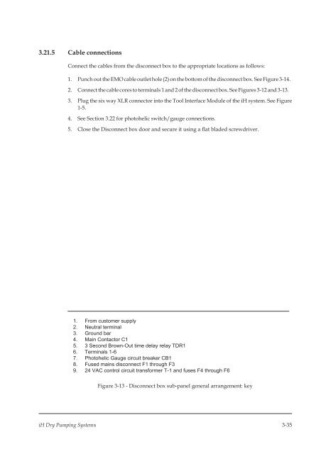
1. From customer supply<br />
2. Neutral terminal<br />
3. Ground bar<br />
4. Main Contactor C1<br />
5. 3 Second Brown-Out time delay relay TDR1<br />
6. Terminals 1-6<br />
7. Photohelic Gauge circuit breaker CB1<br />
8. Fused mains disconnect F1 through F3<br />
9. 24 VAC control circuit transformer T-1 and fuses F4 through F6<br />
Figure 3-13 - Disconnect box sub-panel general arrangement: key<br />
<strong>iH</strong> <strong>Dry</strong> <strong>Pumping</strong> <strong>Systems</strong> 3-35


