

Edwards iH Dry Pumping Systems, iH80, iH600, iH1000
Edwards iH Dry Pumping Systems, iH80, iH600, iH1000
Edwards iH Dry Pumping Systems, iH80, iH600, iH1000

You also want an ePaper? Increase the reach of your titles
YUMPU automatically turns print PDFs into web optimized ePapers that Google loves.
Notes:<br />
On an <strong>iH</strong>1000 system, the earth (ground) installation must ensure that there is an equipotential<br />
zone aroundthe <strong>iH</strong> system: the voltage between the protective earth (ground) studon the <strong>iH</strong><br />
system andany other conducting surface within 2 metres of the <strong>iH</strong> system must be < 30 V r.m.s.<br />
If you connect the electrical supply to an <strong>iH</strong>1000 system through ELCB relays, they must be<br />
suitable for the protection of equipment with a d.c. component in the fault current, and suitable<br />
for short-duration switch-on surges, and for high leakage current (for example, type B, according<br />
to prEN50178).<br />
Use the following procedure to connect the electrical supply to the <strong>iH</strong> system. When you<br />
make your electrical supply cable, ensure that the earth (ground) conductor is longer than the<br />
phase conductors. This will ensure that if the cable is accidentally dragged and the strain<br />
relief bush on the electrical supply connector mating-half fails, the earth (ground) conductor<br />
will be the last conductor to be pulled from the connector.<br />
1. Refer to Figure 3-10. Remove the connector block (8) from the cover (7) of the mating-half<br />
supplied for the electrical supply connector, then pass a suitable cable (6) through the strain<br />
relief bush (5) on the cover (7). Refer to Section 2 for suitable cable sizes.<br />
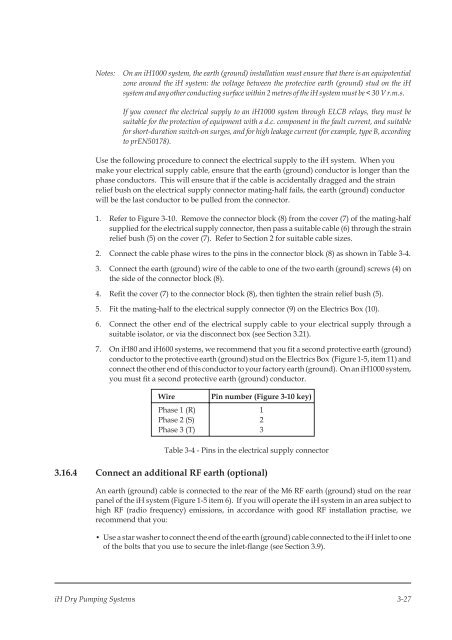
2. Connect the cable phase wires to the pins in the connector block (8) as shown in Table 3-4.<br />
3. Connect the earth (ground) wire of the cable to one of the two earth (ground) screws (4) on<br />
the side of the connector block (8).<br />
4. Refit the cover (7) to the connector block (8), then tighten the strain relief bush (5).<br />
5. Fit the mating-half to the electrical supply connector (9) on the Electrics Box (10).<br />
6. Connect the other end of the electrical supply cable to your electrical supply through a<br />
suitable isolator, or via the disconnect box (see Section 3.21).<br />
7. On <strong>iH</strong>80 and <strong>iH</strong>600 systems, we recommend that you fit a second protective earth (ground)<br />
conductor to the protective earth (ground) stud on the Electrics Box (Figure 1-5, item 11) and<br />
connect the other end of this conductor to your factory earth (ground). On an <strong>iH</strong>1000 system,<br />
you must fit a second protective earth (ground) conductor.<br />
Wire<br />
Phase 1 (R)<br />
Phase 2 (S)<br />
Phase 3 (T)<br />
Pin number (Figure 3-10 key)<br />
1<br />
2<br />
3<br />
Table 3-4 - Pins in the electrical supply connector<br />
3.16.4 Connect an additional RF earth (optional)<br />
An earth (ground) cable is connected to the rear of the M6 RF earth (ground) stud on the rear<br />
panel of the <strong>iH</strong> system (Figure 1-5 item 6). If you will operate the <strong>iH</strong> system in an area subject to<br />
high RF (radio frequency) emissions, in accordance with good RF installation practise, we<br />
recommend that you:<br />
• Use a star washer to connect the end of the earth (ground) cable connected to the <strong>iH</strong> inlet to one<br />
of the bolts that you use to secure the inlet-flange (see Section 3.9).<br />
<strong>iH</strong> <strong>Dry</strong> <strong>Pumping</strong> <strong>Systems</strong> 3-27


