- Page 2:
Reservoir Geomechanics This interdi
- Page 8:
cambridge university press Cambridg
- Page 14:
Contents Preface page xi PART I: BA
- Page 18:
ix Contents More on drilling-induce
- Page 22:
Preface This book has its origin in
- Page 26:
xiii Preface done with Pavel Peska
- Page 34:
1 The tectonic stress field My goal
- Page 38:
5 The tectonic stress field chapter
- Page 42:
7 The tectonic stress field signifi
- Page 46:
9 The tectonic stress field S v Nor
- Page 50:
0 SEAFLOOR 2000 Depth (feet below s
- Page 54:
a. Stress or pressure 0 20 40 60 80
- Page 58:
15 The tectonic stress field The o
- Page 62:
17 The tectonic stress field Observ
- Page 66:
180˚ 216˚ 252˚ 288˚ 324˚ 64˚
- Page 70:
21 The tectonic stress field 121 o
- Page 74:
23 The tectonic stress field 62N 0
- Page 78:
a. Margarita Pays b. Stress state a
- Page 82:
2 Pore pressure at depth in sedimen
- Page 86:
29 Pore pressure at depth in sedime
- Page 90:
31 Pore pressure at depth in sedime
- Page 94:
33 Pore pressure at depth in sedime
- Page 98:
35 Pore pressure at depth in sedime
- Page 102:
37 Pore pressure at depth in sedime
- Page 106:
39 Pore pressure at depth in sedime
- Page 110:
41 Pore pressure at depth in sedime
- Page 114:
43 Pore pressure at depth in sedime
- Page 118:
45 Pore pressure at depth in sedime
- Page 122:
47 Pore pressure at depth in sedime
- Page 126:
a. 2000 OFFSHORE TRINIDAD CENTER OF
- Page 130:
51 Pore pressure at depth in sedime
- Page 134:
53 Pore pressure at depth in sedime
- Page 138:
55 Pore pressure at depth in sedime
- Page 142:
57 Basic constitutive laws a. ELAST
- Page 146:
59 Basic constitutive laws Figure 3
- Page 150:
61 Basic constitutive laws Linear e
- Page 154:
63 Basic constitutive laws Vutukuri
- Page 158:
65 Basic constitutive laws Elastici
- Page 162:
67 Basic constitutive laws a. Stres
- Page 166:
69 Basic constitutive laws depend o
- Page 170:
71 Basic constitutive laws a. 20 18
- Page 174:
a. Confining pressure (MPa) 30 25 2
- Page 178:
75 Basic constitutive laws a. Creep
- Page 182:
a. 30 25 Differential stress (MPa)
- Page 186:
79 Basic constitutive laws a. 1 0.9
- Page 190:
81 Basic constitutive laws where th
- Page 194:
83 Basic constitutive laws the b pa
- Page 198:
85 Rock failure in compression, ten
- Page 202:
87 Rock failure in compression, ten
- Page 206:
89 Rock failure in compression, ten
- Page 210:
91 Rock failure in compression, ten
- Page 214:
93 Rock failure in compression, ten
- Page 218:
95 Rock failure in compression, ten
- Page 222:
s 3 = 30 s 3 = 40 97 Rock failure i
- Page 226:
99 Rock failure in compression, ten
- Page 230:
101 Rock failure in compression, te
- Page 234:
103 Rock failure in compression, te
- Page 238:
105 Rock failure in compression, te
- Page 242:
107 Rock failure in compression, te
- Page 246:
109 Rock failure in compression, te
- Page 250:
a. 200 150 V p (m/s) 4000 2000 1000
- Page 254:
Table 4.1. Empirical relationships
- Page 258:
115 Rock failure in compression, te
- Page 262:
a. 600 500 Frequency (counts) 400 3
- Page 266:
119 Rock failure in compression, te
- Page 270:
121 Rock failure in compression, te
- Page 274:
123 Rock failure in compression, te
- Page 278:
125 Rock failure in compression, te
- Page 282:
127 Rock failure in compression, te
- Page 286:
x x x x x x x x x x x x x x Plate-d
- Page 290:
131 Rock failure in compression, te
- Page 294:
133 Rock failure in compression, te
- Page 298:
a. 0 Stress or pressure 0 20 40 60
- Page 302:
137 Rock failure in compression, te
- Page 306:
139 Rock failure in compression, te
- Page 310:
141 Faults and fractures at depth S
- Page 314:
143 Faults and fractures at depth t
- Page 318:
145 Faults and fractures at depth c
- Page 322:
147 Faults and fractures at depth a
- Page 326:
149 Faults and fractures at depth A
- Page 330:
151 Faults and fractures at depth a
- Page 334:
153 Faults and fractures at depth A
- Page 338:
155 Faults and fractures at depth a
- Page 342:
157 Faults and fractures at depth w
- Page 346:
159 Faults and fractures at depth F
- Page 350:
161 Faults and fractures at depth i
- Page 354:
163 Faults and fractures at depth m
- Page 362:
6 Compressive and tensile failures
- Page 366:
169 Compressive and tensile failure
- Page 370:
. 140 a. 120 100 S hmin S Hmax R S
- Page 374:
173 Compressive and tensile failure
- Page 378:
175 Compressive and tensile failure
- Page 382:
177 Compressive and tensile failure
- Page 386:
a. b. c. 5400 5600 5800 6000 Depth
- Page 390:
181 Compressive and tensile failure
- Page 394:
183 Compressive and tensile failure
- Page 398:
185 Compressive and tensile failure
- Page 402:
187 Compressive and tensile failure
- Page 406:
Table 6.1. Quality ranking system A
- Page 410:
191 Compressive and tensile failure
- Page 414:
193 Compressive and tensile failure
- Page 418:
195 Compressive and tensile failure
- Page 422:
197 Compressive and tensile failure
- Page 426:
199 Compressive and tensile failure
- Page 430:
201 Compressive and tensile failure
- Page 434:
203 Compressive and tensile failure
- Page 438:
205 Compressive and tensile failure
- Page 442:
207 Determination of S 3 from mini-
- Page 446:
209 Determination of S 3 from mini-
- Page 450:
211 Determination of S 3 from mini-
- Page 454:
a. 2500 2 Shut-in Shut-in 2000 1.5
- Page 458:
215 Determination of S 3 from mini-
- Page 462:
217 Determination of S 3 from mini-
- Page 466:
219 Determination of S 3 from mini-
- Page 470:
221 Determination of S 3 from mini-
- Page 474:
223 Determination of S 3 from mini-
- Page 478:
225 Determination of S 3 from mini-
- Page 482:
227 Determination of S 3 from mini-
- Page 486:
229 Determination of S 3 from mini-
- Page 490:
231 Determination of S 3 from mini-
- Page 494:
233 Determination of S 3 from mini-
- Page 498:
8 Wellbore failure and stress deter
- Page 502:
237 Wellbore failure and stress det
- Page 506:
239 Wellbore failure and stress det
- Page 510:
241 Wellbore failure and stress det
- Page 514:
243 Wellbore failure and stress det
- Page 518:
245 Wellbore failure and stress det
- Page 522:
247 Wellbore failure and stress det
- Page 526:
249 Wellbore failure and stress det
- Page 530:
251 Wellbore failure and stress det
- Page 534:
253 Wellbore failure and stress det
- Page 538:
255 Wellbore failure and stress det
- Page 542:
257 Wellbore failure and stress det
- Page 546:
Fast 259 Wellbore failure and stres
- Page 550:
261 Wellbore failure and stress det
- Page 554:
263 Wellbore failure and stress det
- Page 558:
265 Wellbore failure and stress det
- Page 562:
267 Stress fields of the processes
- Page 566:
180˚ 270˚ 0˚ 90˚ 180˚ 70˚ 70
- Page 570:
271 Stress fields collision of two
- Page 574:
273 Stress fields and Schubert 2002
- Page 578:
275 Stress fields essentially perpe
- Page 582:
277 Stress fields 55 Normal faultin
- Page 586:
279 Stress fields and pore pressure
- Page 590:
Table 9.1. Empirical methods for es
- Page 594:
283 Stress fields a. 9100 b. 10000
- Page 598:
285 Stress fields original data com
- Page 602:
287 Stress fields practical importa
- Page 606:
289 Stress fields 0 Strike-slip fau
- Page 610:
291 Stress fields 0 Reverse faultin
- Page 614:
293 Stress fields Log data Density
- Page 618:
295 Stress fields 2050 2050 S hmin
- Page 622:
297 Stress fields depth (Figure 9.1
- Page 630:
10 Wellbore stability In this chapt
- Page 634:
303 Wellbore stability et al. 2003)
- Page 638:
305 Wellbore stability a. Predicted
- Page 642:
307 Wellbore stability a. Equivalen
- Page 646:
309 Wellbore stability S Hmax N S h
- Page 650:
311 Wellbore stability 60 80 100 12
- Page 654:
313 Wellbore stability a. b. c. 6.5
- Page 658:
315 Wellbore stability 12 10 8 6 4
- Page 662:
317 Wellbore stability a. b. 100 10
- Page 666:
319 Wellbore stability of the forma
- Page 670:
321 Wellbore stability part of Figu
- Page 674:
323 Wellbore stability a. 15.8 15.6
- Page 678:
325 Wellbore stability S 3 P grow P
- Page 682:
327 Wellbore stability pressures -
- Page 686:
329 Wellbore stability 90 80 70 60
- Page 690:
331 Wellbore stability sandstones a
- Page 694:
333 Wellbore stability This type of
- Page 698:
335 Wellbore stability Figure 10.22
- Page 702:
337 Wellbore stability Figure 10.24
- Page 706:
339 Wellbore stability and drawdown
- Page 710:
341 Critically stressed faults and
- Page 714:
343 Critically stressed faults and
- Page 718:
345 Critically stressed faults and
- Page 722:
347 Critically stressed faults and
- Page 726:
349 Critically stressed faults and
- Page 730:
351 Critically stressed faults and
- Page 734:
353 Critically stressed faults and
- Page 738:
a. Available test wells Observation
- Page 742:
357 Critically stressed faults and
- Page 746:
Breakout orientation (N o E) 0 90 1
- Page 750:
361 Critically stressed faults and
- Page 754:
363 Critically stressed faults and
- Page 758:
365 Critically stressed faults and
- Page 762:
367 Critically stressed faults and
- Page 766:
369 Critically stressed faults and
- Page 770:
371 Critically stressed faults and
- Page 774:
373 Critically stressed faults and
- Page 778:
SSTAVD (feet) 375 Critically stress
- Page 782:
377 Critically stressed faults and
- Page 786:
379 Effects of reservoir depletion
- Page 790:
381 Effects of reservoir depletion
- Page 794:
383 Effects of reservoir depletion
- Page 798:
385 Effects of reservoir depletion
- Page 802:
387 Effects of reservoir depletion
- Page 806:
389 Effects of reservoir depletion
- Page 810:
Figure 12.6. (a) Cartoon of a hypot
- Page 814:
393 Effects of reservoir depletion
- Page 818:
395 Effects of reservoir depletion
- Page 822:
397 Effects of reservoir depletion
- Page 826:
399 Effects of reservoir depletion
- Page 830:
401 Effects of reservoir depletion
- Page 834:
403 Effects of reservoir depletion
- Page 838:
405 Effects of reservoir depletion
- Page 842:
407 Effects of reservoir depletion
- Page 846:
409 Effects of reservoir depletion
- Page 850:
411 Effects of reservoir depletion
- Page 854:
413 Effects of reservoir depletion
- Page 858:
415 Effects of reservoir depletion
- Page 862:
417 Effects of reservoir depletion
- Page 866:
419 Effects of reservoir depletion
- Page 870:
421 Effects of reservoir depletion
- Page 876:
424 References Baria, R., Baumgaerd
- Page 880:
426 References Carmichael, R. S. (1
- Page 884:
428 References Ekstrom, M. P., Daha
- Page 888:
430 References Grollimund, B. R. an
- Page 892:
432 References Hudson, J. A. and Pr
- Page 896:
434 References Mastin, L. (1988).
- Page 900:
436 References Ostermeier, R. M. (2
- Page 904:
438 References 71337. SPE Annual Te
- Page 908:
440 References Van Oort, E., Hale,
- Page 912:
442 References Zoback, M. D., Apel,
- Page 918:
Index σ rr , radial stress 91, 170
- Page 922:
447 Index slick-water frac’ing 36
- Page 926:
449 Index washouts 184, 243 weak be
- Page 936:
a. b. c. Pore pressure at 1500 m de
- Page 940:
a. W Shot Number E 1300 1400 1500 1
- Page 944:
a. 160 140 Stress at wellbore wall
- Page 948:
a. 150 Stress at wellbore wall (MPa
- Page 952: a. 150 s qq at azimuth of S Hmax (M
- Page 956: a. -400 0 400 0 50 100 15.5 16 16.5
- Page 960: a. Normal b. Strike-Slip c. Reverse
- Page 964: a. Horizontal distance west (m) Dev
- Page 968: 3 o W 64 o N Stress trajectories a.
- Page 972: 60 80 100 120 140 160 180 Breakout
- Page 976: a. N b. N W E W E S S MW = 12 ppg 1
- Page 980: MW (ppg) 14 12 10 8 6 a. Range of m
- Page 984: a. b. 4200 4000 3800 3600 3400 BOTT
- Page 988: CAJON PASS NTS G-1 LONG VALLEY HYDR
- Page 992: t/S v −1 .8 .6 .4 .2 0 0 1.5 2 1.
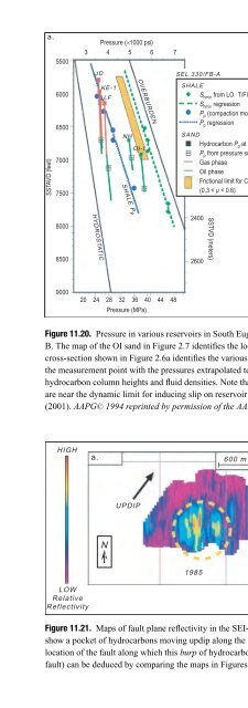
- Page 996: Figure 11.8. (a) Location map of th
- Page 1000: N EXTENT OF GAS LEAKAGE D C B 2550
- Page 1006: N Vertical Displacement cm 2 N East