- Page 1:
Open Source Software for Train Cont
- Page 4 and 5:
Datum des Promotionskolloquiums: 21
- Page 7 and 8:
Acknowledgments I would like to tha
- Page 9:
Abstract This document describes th
- Page 12 and 13:
Contents 3.3.3. Rascal . . . . . .
- Page 14 and 15:
Contents 8.4. Behavioural Design .
- Page 16 and 17:
Contents D.3. Domain Framework Mode
- Page 18 and 19:
List of Figures 6.4. Simple CORBA u
- Page 20 and 21:
List of Figures 10.27. General read
- Page 22 and 23:
Chapter 1. Introduction Railway Con
- Page 24 and 25:
Chapter 1. Introduction MontiCore M
- Page 26 and 27:
Chapter 1. Introduction ERTMS Forma
- Page 29:
Part I. Background 9
- Page 32 and 33:
Chapter 2. Concepts for Safe Railwa
- Page 34 and 35:
Chapter 2. Concepts for Safe Railwa
- Page 36 and 37:
Chapter 2. Concepts for Safe Railwa
- Page 38 and 39:
Chapter 2. Concepts for Safe Railwa
- Page 40 and 41:
Chapter 2. Concepts for Safe Railwa
- Page 42 and 43:
Chapter 3. Domain-Specific Modellin
- Page 44 and 45:
Chapter 3. Domain-Specific Modellin
- Page 46 and 47:
Chapter 3. Domain-Specific Modellin
- Page 48 and 49:
Chapter 3. Domain-Specific Modellin
- Page 50 and 51:
Chapter 3. Domain-Specific Modellin
- Page 52 and 53:
Chapter 3. Domain-Specific Modellin
- Page 54 and 55:
Chapter 3. Domain-Specific Modellin
- Page 56 and 57:
Chapter 3. Domain-Specific Modellin
- Page 59 and 60:
4The GOPPRR Meta Meta Model - An Ex
- Page 61 and 62:
4.1. Concrete Syntax Description Fo
- Page 63 and 64:
4.2. GOPPRR C++ Abstract Syntax Mod
- Page 65 and 66:
4.2. GOPPRR C++ Abstract Syntax Mod
- Page 67 and 68:
4.5. The Object Constraint Language
- Page 69 and 70:
4.5. The Object Constraint Language
- Page 71 and 72:
4.6. Tool Chain where artefacts are
- Page 73 and 74:
4.7. Conclusion External Artefacts
- Page 75:
Part II. Dependability 55
- Page 78 and 79:
Chapter 5. Verification and Validat
- Page 80 and 81:
Chapter 5. Verification and Validat
- Page 82 and 83:
Chapter 5. Verification and Validat
- Page 85 and 86:
6Security in Open Source Software A
- Page 87 and 88:
6.1. Memory Management Open Meta Me
- Page 89 and 90:
6.2. Hardware Virtualisation a fixe
- Page 91 and 92:
6.2. Hardware Virtualisation in a v
- Page 93 and 94:
6.2. Hardware Virtualisation Again,
- Page 95 and 96:
6.2. Hardware Virtualisation the fa
- Page 97:
Part III. openETCS Case Study 77
- Page 100 and 101:
Chapter 7. openETCS Meta Model far
- Page 102 and 103:
Chapter 7. openETCS Meta Model gEVC
- Page 104 and 105:
Chapter 7. openETCS Meta Model gEVC
- Page 106 and 107:
Chapter 7. openETCS Meta Model gMai
- Page 108 and 109:
Chapter 7. openETCS Meta Model Outp
- Page 110 and 111:
Chapter 7. openETCS Meta Model thei
- Page 112 and 113:
Chapter 7. openETCS Meta Model gSub
- Page 114 and 115:
Chapter 7. openETCS Meta Model The
- Page 116 and 117:
Chapter 7. openETCS Meta Model can
- Page 118 and 119:
Chapter 7. openETCS Meta Model The
- Page 120 and 121:
Chapter 7. openETCS Meta Model List
- Page 122 and 123:
Chapter 7. openETCS Meta Model 5 s
- Page 124 and 125:
Chapter 7. openETCS Meta Model 7.5.
- Page 126 and 127:
Chapter 7. openETCS Meta Model 12 )
- Page 128 and 129:
Chapter 7. openETCS Meta Model 7.5.
- Page 130 and 131:
Chapter 7. openETCS Meta Model Thus
- Page 132 and 133:
Chapter 7. openETCS Meta Model In t
- Page 134 and 135:
Chapter 7. openETCS Meta Model Valu
- Page 136 and 137:
Chapter 7. openETCS Meta Model This
- Page 138 and 139:
Chapter 7. openETCS Meta Model and
- Page 140 and 141:
Chapter 7. openETCS Meta Model 7.8.
- Page 142 and 143:
Chapter 8. openETCS Domain Framewor
- Page 144 and 145:
Chapter 8. openETCS Domain Framewor
- Page 146 and 147:
Chapter 8. openETCS Domain Framewor
- Page 148 and 149:
Chapter 8. openETCS Domain Framewor
- Page 150 and 151:
Chapter 8. openETCS Domain Framewor
- Page 152 and 153:
Chapter 8. openETCS Domain Framewor
- Page 154 and 155:
Chapter 8. openETCS Domain Framewor
- Page 156 and 157:
Chapter 8. openETCS Domain Framewor
- Page 158 and 159:
Chapter 8. openETCS Domain Framewor
- Page 160 and 161:
Chapter 8. openETCS Domain Framewor
- Page 162 and 163:
Chapter 8. openETCS Domain Framewor
- Page 164 and 165:
Chapter 8. openETCS Domain Framewor
- Page 166 and 167:
Chapter 8. openETCS Domain Framewor
- Page 168 and 169:
Chapter 8. openETCS Domain Framewor
- Page 170 and 171: Chapter 8. openETCS Domain Framewor
- Page 172 and 173: Chapter 8. openETCS Domain Framewor
- Page 174 and 175: Chapter 8. openETCS Domain Framewor
- Page 176 and 177: Chapter 8. openETCS Domain Framewor
- Page 178 and 179: Chapter 8. openETCS Domain Framewor
- Page 180 and 181: Chapter 9. openETCS Generator Appli
- Page 182 and 183: Chapter 9. openETCS Generator Appli
- Page 184 and 185: Chapter 9. openETCS Generator Appli
- Page 186 and 187: Chapter 9. openETCS Generator Appli
- Page 188 and 189: Chapter 9. openETCS Generator Appli
- Page 190 and 191: Chapter 9. openETCS Generator Appli
- Page 192 and 193: Chapter 9. openETCS Generator Appli
- Page 194 and 195: Chapter 9. openETCS Generator Appli
- Page 196 and 197: Chapter 9. openETCS Generator Appli
- Page 198 and 199: Chapter 9. openETCS Generator Appli
- Page 200 and 201: Chapter 10. openETCS Model No Power
- Page 202 and 203: Chapter 10. openETCS Model c4 bool
- Page 204 and 205: Chapter 10. openETCS Model c1 c8 c1
- Page 206 and 207: Chapter 10. openETCS Model Applicat
- Page 208 and 209: Chapter 10. openETCS Model c1 c25 c
- Page 210 and 211: Chapter 10. openETCS Model Initiali
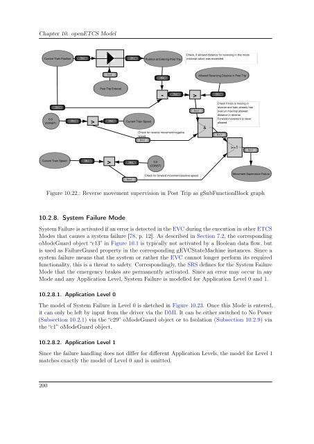
- Page 212 and 213: Chapter 10. openETCS Model Reverse
- Page 214 and 215: Chapter 10. openETCS Model 0 (CONST
- Page 216 and 217: Chapter 10. openETCS Model Current
- Page 218 and 219: Chapter 10. openETCS Model c7 bool
- Page 222 and 223: Chapter 10. openETCS Model The purp
- Page 224 and 225: Chapter 10. openETCS Model 10.3.3.
- Page 226 and 227: Chapter 10. openETCS Model be expla
- Page 228 and 229: Chapter 10. openETCS Model 10.4.4.
- Page 231 and 232: 11 openETCS Simulation Generally, a
- Page 233 and 234: 11.2. Platform Specific Model for t
- Page 235 and 236: 11.2. Platform Specific Model for t
- Page 237 and 238: 11.2. Platform Specific Model for t
- Page 239 and 240: 11.3. Simulation Model Figure 11.6.
- Page 241 and 242: 11.3. Simulation Model 11.3.2. CDMI
- Page 243 and 244: 11.3. Simulation Model sets the Boo
- Page 245 and 246: 11.3. Simulation Model Entering_Dri
- Page 247 and 248: 11.3. Simulation Model The states o
- Page 249 and 250: 11.3. Simulation Model Figure 11.13
- Page 251 and 252: 11.3. Simulation Model Figure 11.14
- Page 253 and 254: 11.3. Simulation Model Figure 11.15
- Page 255: 11.6. Conclusion about warnings, fa
- Page 258 and 259: Chapter 12. Conclusion and Outlook
- Page 261: Part IV. Appendix 241
- Page 264 and 265: Appendix A. GOPPRR to MOF Transform
- Page 266 and 267: Appendix B. openETCS Meta Model Con
- Page 268 and 269: Appendix B. openETCS Meta Model Con
- Page 270 and 271:
Appendix B. openETCS Meta Model Con
- Page 273 and 274:
DopenETCS Domain Framework D.1. Dom
- Page 275 and 276:
D.2. Domain Framework Source Code 8
- Page 277:
D.3. Domain Framework Model 32 m_pT
- Page 280 and 281:
Appendix E. openETCS Generator 39 <
- Page 282 and 283:
Appendix E. openETCS Generator 200
- Page 284 and 285:
Appendix E. openETCS Generator 46 4
- Page 287 and 288:
FMetaEdit+ Generators F.1. GOPPRR X
- Page 289:
GopenETCS Unit Testing G.1. Unit Te
- Page 292 and 293:
Appendix H. openETCS Simulation 14
- Page 294 and 295:
Appendix H. openETCS Simulation 25
- Page 296 and 297:
Appendix H. openETCS Simulation 229
- Page 299 and 300:
Glossary ANTLR ANother Tool for Lan
- Page 301 and 302:
Glossary EVC An European Vital Comp
- Page 303 and 304:
Glossary OEM An original equipment
- Page 305:
Glossary XML The Extensible Markup
- Page 308 and 309:
Bibliography [12] “EN 50128 - Rai
- Page 310 and 311:
Bibliography [39] ——, ““Ope
- Page 312 and 313:
Bibliography [69] T. J. Parr and R.
- Page 315 and 316:
Index Artefact, 51 Automatic train
- Page 317 and 318:
Index Linux, 149 Memory management,