

POLITECHNIKA WARSZAWSKA
POLITECHNIKA WARSZAWSKA
POLITECHNIKA WARSZAWSKA

Create successful ePaper yourself
Turn your PDF publications into a flip-book with our unique Google optimized e-Paper software.
7. Simulation and experimental results<br />
7.3. Steady state behaviour<br />
The simulation and experimental results obtained in steady state for the system<br />
described in the previous chapter are presented in Fig. 7.3-Fig. 7.20.<br />
The first part of these graphs (Fig. 7.3.-Fig. 7.11) corresponds to the system<br />
with measured speed taken to the feedback and coordinate transformation. These<br />
investigations have been performed to show the behaviour of the FOC system,<br />
without influence of the speed estimation. In these graphs estimated speed, stator<br />
phase current, rotor flux component and electromagnetic torque are shown, for<br />
different values of the mechanical speed and load torque. Note that the bahaviour of<br />
the system in steady state is correct and the simulation results are similar to the<br />
experimental ones.<br />
The second part of graphs (Fig. 7.12-Fig. 7.20) corresponds to the system with<br />
estimated speed taken to the feedback and coordinate transformation. These results<br />
confirm the good behaviour of neural network speed estimator.<br />
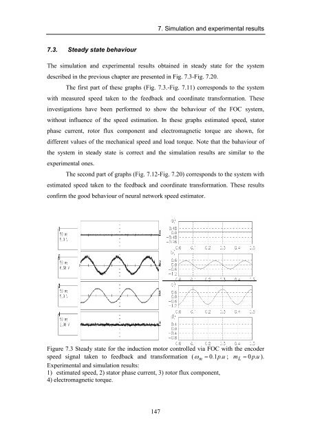
Figure 7.3 Steady state for the induction motor controlled via FOC with the encoder<br />
speed signal taken to feedback and transformation ( ω m = 0.1p.<br />
u ; m L = 0 p.<br />
u ).<br />
Experimental and simulation results:<br />
1) estimated speed, 2) stator phase current, 3) rotor flux component,<br />
4) electromagnetic torque.<br />
147


![[TCP] Opis układu - Instytut Sterowania i Elektroniki Przemysłowej ...](https://img.yumpu.com/23535443/1/184x260/tcp-opis-ukladu-instytut-sterowania-i-elektroniki-przemyslowej-.jpg?quality=85)
