

POLITECHNIKA WARSZAWSKA
POLITECHNIKA WARSZAWSKA
POLITECHNIKA WARSZAWSKA

You also want an ePaper? Increase the reach of your titles
YUMPU automatically turns print PDFs into web optimized ePapers that Google loves.
4. ANN based Current Controllers (CC)<br />
switching frequency, well-defined harmonic spectrum, optimum switch pattern and<br />
DC link utilisation. Also, full independent design of the overall control structure as<br />
well as open loop testing of the inverter and load can be easily performed. In the<br />
linear group, the following controllers are described: PI stationary and synchronous,<br />
state feedback, predictive with constant switching frequency.<br />
A. Stationary controller PI<br />
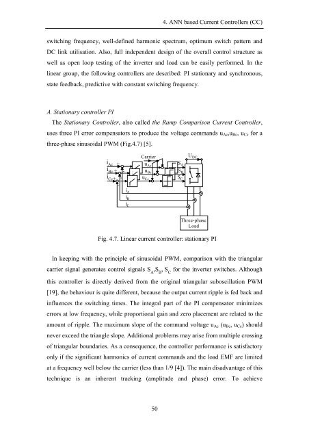
The Stationary Controller, also called the Ramp Comparison Current Controller,<br />
uses three PI error compensators to produce the voltage commands u Ac ,u Bc , u Cc for a<br />
three-phase sinusoidal PWM (Fig.4.7) [5].<br />
i Ac +<br />
i Bc + -<br />
i Cc + -<br />
-<br />
Carrier<br />
u Ac<br />
u Bc<br />
u Cc<br />
S A<br />
S B<br />
S C<br />
U DC<br />
i A<br />
i B<br />
i C<br />
Three-phase<br />
Load<br />
Fig. 4.7. Linear current controller: stationary PI<br />
In keeping with the principle of sinusoidal PWM, comparison with the triangular<br />
carrier signal generates control signals S A<br />
,S B<br />
, S C<br />
for the inverter switches. Although<br />
this controller is directly derived from the original triangular suboscillation PWM<br />
[19], the behaviour is quite different, because the output current ripple is fed back and<br />
influences the switching times. The integral part of the PI compensator minimizes<br />
errors at low frequency, while proportional gain and zero placement are related to the<br />
amount of ripple. The maximum slope of the command voltage u Ac (u Bc , u Cc ) should<br />
never exceed the triangle slope. Additional problems may arise from multiple crossing<br />
of triangular boundaries. As a consequence, the controller performance is satisfactory<br />
only if the significant harmonics of current commands and the load EMF are limited<br />
at a frequency well below the carrier (less than 1/9 [4]). The main disadvantage of this<br />
technique is an inherent tracking (amplitude and phase) error. To achieve<br />
50


![[TCP] Opis układu - Instytut Sterowania i Elektroniki Przemysłowej ...](https://img.yumpu.com/23535443/1/184x260/tcp-opis-ukladu-instytut-sterowania-i-elektroniki-przemyslowej-.jpg?quality=85)
