TITRE Adaptive Packet Video Streaming Over IP Networks - LaBRI
TITRE Adaptive Packet Video Streaming Over IP Networks - LaBRI
TITRE Adaptive Packet Video Streaming Over IP Networks - LaBRI

You also want an ePaper? Increase the reach of your titles
YUMPU automatically turns print PDFs into web optimized ePapers that Google loves.
4.2.3.1.2 Scenario 2<br />
In this scenario, we demonstrate the effect of the unequal error protection (UEP) of our RTP<br />
payload. The transmitted MPEG-4 scene is composed of a set of Audio Visual Objects (AVOs).<br />
The first object (O1) is a 25-fps video stream composed of 3 hierarchical layers (Base Layer,<br />
Enhancement Layer 1 and Enhancement Layer 2). The second object (O2) is also a 25-fps video<br />
stream composed of one single layer. Finally, the last object (O3) is an AAC audio stream. The<br />
instantaneous throughput of each object during one-minute is described as follows. The full<br />
MPEG-4 scene has an average rate of 770 Kbits/s and a peak rate of 1460 Kbits/s. Assume that<br />
the audio (O3) has the higher priority score than O2 which have a higher priority score than O1 in<br />
the MPEG-4 scene. Diffserv marking uses this information and marks each object stream by a<br />
Diffserv code point to reflect a particular Diffserv class of service (high drop, low drop, etc.).<br />
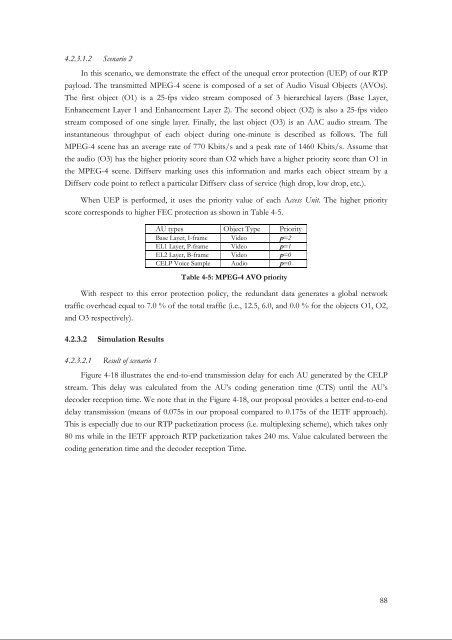
When UEP is performed, it uses the priority value of each Access Unit. The higher priority<br />
score corresponds to higher FEC protection as shown in Table 4-5.<br />
AU types Object Type Priority<br />
Base Layer, I-frame <strong>Video</strong> p=2<br />
EL1 Layer, P-frame <strong>Video</strong> p=1<br />
EL2 Layer, B-frame <strong>Video</strong> p=0<br />
CELP Voice Sample Audio p=0<br />
Table 4-5: MPEG-4 AVO priority<br />
With respect to this error protection policy, the redundant data generates a global network<br />
traffic overhead equal to 7.0 % of the total traffic (i.e., 12.5, 6.0, and 0.0 % for the objects O1, O2,<br />
and O3 respectively).<br />
4.2.3.2 Simulation Results<br />
4.2.3.2.1 Result of scenario 1<br />
Figure 4-18 illustrates the end-to-end transmission delay for each AU generated by the CELP<br />
stream. This delay was calculated from the AU’s coding generation time (CTS) until the AU’s<br />
decoder reception time. We note that in the Figure 4-18, our proposal provides a better end-to-end<br />
delay transmission (means of 0.075s in our proposal compared to 0.175s of the IETF approach).<br />
This is especially due to our RTP packetization process (i.e. multiplexing scheme), which takes only<br />
80 ms while in the IETF approach RTP packetization takes 240 ms. Value calculated between the<br />
coding generation time and the decoder reception Time.<br />
88