

cmd6686gx manual - RTD Embedded Technologies, Inc.
cmd6686gx manual - RTD Embedded Technologies, Inc.
cmd6686gx manual - RTD Embedded Technologies, Inc.

You also want an ePaper? Increase the reach of your titles
YUMPU automatically turns print PDFs into web optimized ePapers that Google loves.
Jumpers<br />
Many cpuModule options are configured by positioning jumpers. Jumpers are labeled on the board<br />
as “JP” followed by a number.<br />
Some jumpers are three pins, allowing three settings:<br />
• pins 1 and 2 connected (indicated as "1-2")<br />
• pins 2 and 3 connected (indicated as "2-3")<br />
• no pins connected.<br />
1 2 3<br />
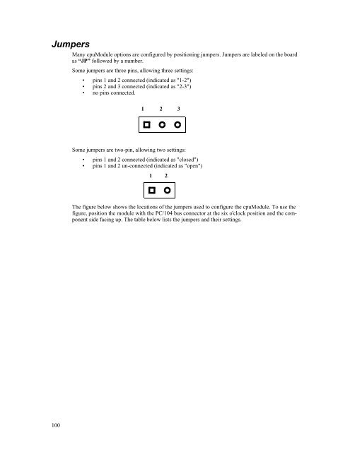
Some jumpers are two-pin, allowing two settings:<br />
• pins 1 and 2 connected (indicated as "closed")<br />
• pins 1 and 2 un-connected (indicated as "open")<br />
1 2<br />
The figure below shows the locations of the jumpers used to configure the cpuModule. To use the<br />
figure, position the module with the PC/104 bus connector at the six o'clock position and the component<br />
side facing up. The table below lists the jumpers and their settings.<br />
100


