

cmd6686gx manual - RTD Embedded Technologies, Inc.
cmd6686gx manual - RTD Embedded Technologies, Inc.
cmd6686gx manual - RTD Embedded Technologies, Inc.

You also want an ePaper? Increase the reach of your titles
YUMPU automatically turns print PDFs into web optimized ePapers that Google loves.
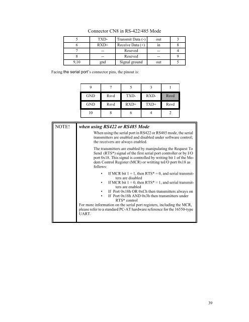
Connector CN8 in RS-422/485 Mode<br />
5 TXD- Transmit Data (-) out 3<br />
6 RXD+ Receive Data (+) in 8<br />
7 -- Reseved -- 4<br />
8 -- Reseved -- 9<br />
9,10 gnd Signal ground out 5<br />
Facing the serial port’s connector pins, the pinout is:<br />
9 7 5 3 1<br />
GND Rsvd TXD- RXD- Rsvd<br />
GND Rsvd RXD+ TXD+ Rsvd<br />
10 8 6 4 2<br />
NOTE!<br />
when using RS422 or RS485 Mode<br />
When using the serial port in RS422 or RS485 mode, the serial<br />
transmitters are enabled and disabled under software control;<br />
the receivers are always enabled.<br />
The transmitters are enabled by manipulating the Request To<br />
Send (RTS*) signal of the first serial port controller or by I/O<br />
port 0x18. This signal is controlled by writing bit 1 of the Modem<br />
Control Register (MCR) or writting toI/O port 0x18 as<br />
follows:<br />
• If MCR bit 1 = 1, then RTS* = 0, and serial transmitters<br />
are disabled<br />
• If MCR bit 1 = 0, then RTS* = 1, and serial transmitters<br />
are enabled<br />
• If Port 0x18h OR 0xCh then transmitters always on<br />
• If Port 0x18h AND 0x3h then transmitters under<br />
RTS* control<br />
For more information on the serial port registers, including the MCR,<br />
please refer to a standard PC-AT hardware reference for the 16550-type<br />
UART.<br />
39


