

technical manual for sailor compact hf ssb t2130 - Gopher Proxy
technical manual for sailor compact hf ssb t2130 - Gopher Proxy
technical manual for sailor compact hf ssb t2130 - Gopher Proxy

You also want an ePaper? Increase the reach of your titles
YUMPU automatically turns print PDFs into web optimized ePapers that Google loves.
2 INSTALLATION MECHANICAL HF SSB TRANSMITTER T2130<br />
26190<br />
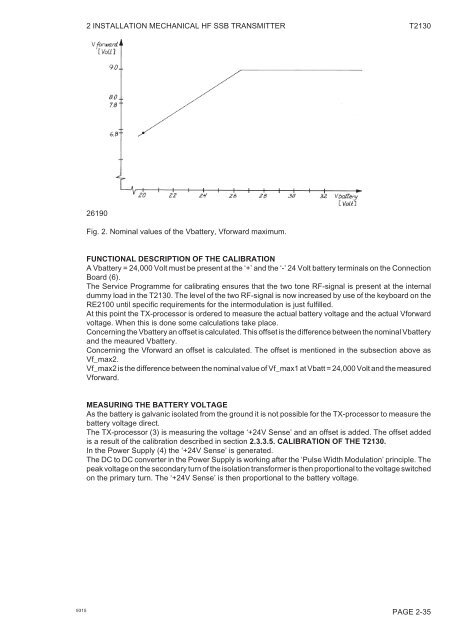
Fig. 2. Nominal values of the Vbattery, V<strong>for</strong>ward maximum.<br />
FUNCTIONAL DESCRIPTION OF THE CALIBRATION<br />
A Vbattery = 24,000 Volt must be present at the ‘+’ and the ‘-’ 24 Volt battery terminals on the Connection<br />
Board (6).<br />
The Service Programme <strong>for</strong> calibrating ensures that the two tone RF-signal is present at the internal<br />
dummy load in the T2130. The level of the two RF-signal is now increased by use of the keyboard on the<br />
RE2100 until specific requirements <strong>for</strong> the intermodulation is just fulfilled.<br />
At this point the TX-processor is ordered to measure the actual battery voltage and the actual V<strong>for</strong>ward<br />
voltage. When this is done some calculations take place.<br />
Concerning the Vbattery an offset is calculated. This offset is the difference between the nominal Vbattery<br />
and the meaured Vbattery.<br />
Concerning the V<strong>for</strong>ward an offset is calculated. The offset is mentioned in the subsection above as<br />
Vf_max2.<br />
Vf_max2 is the difference between the nominal value of Vf_max1 at Vbatt = 24,000 Volt and the measured<br />
V<strong>for</strong>ward.<br />
MEASURING THE BATTERY VOLTAGE<br />
As the battery is galvanic isolated from the ground it is not possible <strong>for</strong> the TX-processor to measure the<br />
battery voltage direct.<br />
The TX-processor (3) is measuring the voltage ‘+24V Sense’ and an offset is added. The offset added<br />
is a result of the calibration described in section 2.3.3.5. CALIBRATION OF THE T2130.<br />
In the Power Supply (4) the ‘+24V Sense’ is generated.<br />
The DC to DC converter in the Power Supply is working after the ‘Pulse Width Modulation’ principle. The<br />
peak voltage on the secondary turn of the isolation trans<strong>for</strong>mer is then proportional to the voltage switched<br />
on the primary turn. The ‘+24V Sense’ is then proportional to the battery voltage.<br />
9315<br />
PAGE 2-35


