

Impact of fuel supply impedance and fuel staging on gas turbine ...
Impact of fuel supply impedance and fuel staging on gas turbine ...
Impact of fuel supply impedance and fuel staging on gas turbine ...

Create successful ePaper yourself
Turn your PDF publications into a flip-book with our unique Google optimized e-Paper software.
6.1 Practical premixed combustor c<strong>on</strong>figurati<strong>on</strong><br />
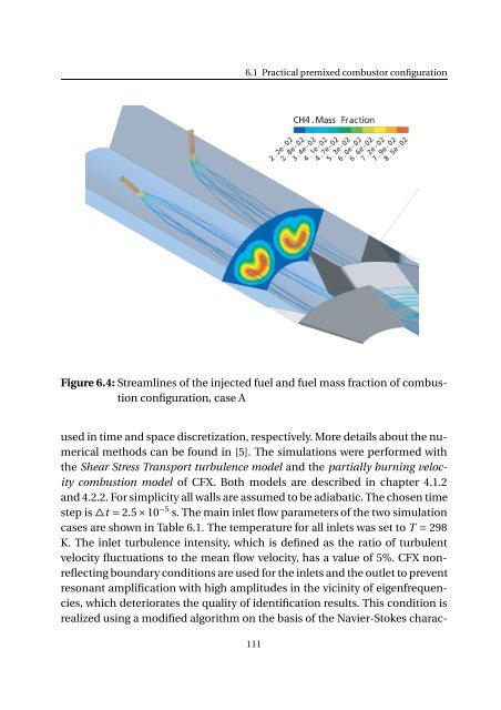
Figure 6.4: Streamlines <str<strong>on</strong>g>of</str<strong>on</strong>g> the injected <str<strong>on</strong>g>fuel</str<strong>on</strong>g> <str<strong>on</strong>g>and</str<strong>on</strong>g> <str<strong>on</strong>g>fuel</str<strong>on</strong>g> mass fracti<strong>on</strong> <str<strong>on</strong>g>of</str<strong>on</strong>g> combusti<strong>on</strong><br />
c<strong>on</strong>figurati<strong>on</strong>, case A<br />
used in time <str<strong>on</strong>g>and</str<strong>on</strong>g> space discretizati<strong>on</strong>, respectively. More details about the numerical<br />
methods can be found in [5]. The simulati<strong>on</strong>s were performed with<br />
the Shear Stress Transport turbulence model <str<strong>on</strong>g>and</str<strong>on</strong>g> the partially burning velocity<br />
combusti<strong>on</strong> model <str<strong>on</strong>g>of</str<strong>on</strong>g> CFX. Both models are described in chapter 4.1.2<br />
<str<strong>on</strong>g>and</str<strong>on</strong>g> 4.2.2. For simplicity all walls are assumed to be adiabatic. The chosen time<br />
step is△t = 2.5×10 −5 s. The main inlet flow parameters <str<strong>on</strong>g>of</str<strong>on</strong>g> the two simulati<strong>on</strong><br />
cases are shown in Table 6.1. The temperature for all inlets was set to T = 298<br />
K. The inlet turbulence intensity, which is defined as the ratio <str<strong>on</strong>g>of</str<strong>on</strong>g> turbulent<br />
velocity fluctuati<strong>on</strong>s to the mean flow velocity, has a value <str<strong>on</strong>g>of</str<strong>on</strong>g> 5%. CFX n<strong>on</strong>reflecting<br />
boundary c<strong>on</strong>diti<strong>on</strong>s are used for the inlets <str<strong>on</strong>g>and</str<strong>on</strong>g> the outlet to prevent<br />
res<strong>on</strong>ant amplificati<strong>on</strong> with high amplitudes in the vicinity <str<strong>on</strong>g>of</str<strong>on</strong>g> eigenfrequencies,<br />
which deteriorates the quality <str<strong>on</strong>g>of</str<strong>on</strong>g> identificati<strong>on</strong> results. This c<strong>on</strong>diti<strong>on</strong> is<br />
realized using a modified algorithm <strong>on</strong> the basis <str<strong>on</strong>g>of</str<strong>on</strong>g> the Navier-Stokes charac-<br />
111


