Impact of fuel supply impedance and fuel staging on gas turbine ...
Impact of fuel supply impedance and fuel staging on gas turbine ...
Impact of fuel supply impedance and fuel staging on gas turbine ...
Create successful ePaper yourself
Turn your PDF publications into a flip-book with our unique Google optimized e-Paper software.
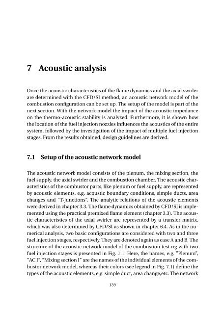
7 Acoustic analysis<br />
Once the acoustic characteristics <str<strong>on</strong>g>of</str<strong>on</strong>g> the flame dynamics <str<strong>on</strong>g>and</str<strong>on</strong>g> the axial swirler<br />
are determined with the CFD/SI method, an acoustic network model <str<strong>on</strong>g>of</str<strong>on</strong>g> the<br />
combusti<strong>on</strong> c<strong>on</strong>figurati<strong>on</strong> can be set up. The setup <str<strong>on</strong>g>of</str<strong>on</strong>g> the model is part <str<strong>on</strong>g>of</str<strong>on</strong>g> the<br />
next secti<strong>on</strong>. With the network model the impact <str<strong>on</strong>g>of</str<strong>on</strong>g> the acoustic <str<strong>on</strong>g>impedance</str<strong>on</strong>g><br />
<strong>on</strong> the thermo-acoustic stability is analyzed. Furthermore, it is shown how<br />
the locati<strong>on</strong> <str<strong>on</strong>g>of</str<strong>on</strong>g> the <str<strong>on</strong>g>fuel</str<strong>on</strong>g> injecti<strong>on</strong> nozzles influences the acoustics <str<strong>on</strong>g>of</str<strong>on</strong>g> the entire<br />
system, followed by the investigati<strong>on</strong> <str<strong>on</strong>g>of</str<strong>on</strong>g> the impact <str<strong>on</strong>g>of</str<strong>on</strong>g> multiple <str<strong>on</strong>g>fuel</str<strong>on</strong>g> injecti<strong>on</strong><br />
stages. From the results obtained, design guidelines are derived.<br />
7.1 Setup <str<strong>on</strong>g>of</str<strong>on</strong>g> the acoustic network model<br />
The acoustic network model c<strong>on</strong>sists <str<strong>on</strong>g>of</str<strong>on</strong>g> the plenum, the mixing secti<strong>on</strong>, the<br />
<str<strong>on</strong>g>fuel</str<strong>on</strong>g> <str<strong>on</strong>g>supply</str<strong>on</strong>g>, the axial swirler <str<strong>on</strong>g>and</str<strong>on</strong>g> the combusti<strong>on</strong> chamber. The acoustic characteristics<br />
<str<strong>on</strong>g>of</str<strong>on</strong>g> the combustor parts, like plenum or <str<strong>on</strong>g>fuel</str<strong>on</strong>g> <str<strong>on</strong>g>supply</str<strong>on</strong>g>, are represented<br />
by acoustic elements, e.g. acoustic boundary c<strong>on</strong>diti<strong>on</strong>s, simple ducts, area<br />
changes <str<strong>on</strong>g>and</str<strong>on</strong>g> ”T-juncti<strong>on</strong>s”. The analytic relati<strong>on</strong>s <str<strong>on</strong>g>of</str<strong>on</strong>g> the acoustic elements<br />
were derived in chapter 3.3. The flame dynamics obtained by CFD/SI is implemented<br />
using the practical premixed flame element (chapter 3.3). The acoustic<br />
characteristics <str<strong>on</strong>g>of</str<strong>on</strong>g> the axial swirler are represented by a transfer matrix,<br />
which was also determined by CFD/SI as shown in chapter 6.4. As in the numerical<br />
analysis, two basic c<strong>on</strong>figurati<strong>on</strong>s are c<strong>on</strong>sidered with two <str<strong>on</strong>g>and</str<strong>on</strong>g> three<br />
<str<strong>on</strong>g>fuel</str<strong>on</strong>g> injecti<strong>on</strong> stages, respectively. They are denoted again as case A <str<strong>on</strong>g>and</str<strong>on</strong>g> B. The<br />
structure <str<strong>on</strong>g>of</str<strong>on</strong>g> the acoustic network model <str<strong>on</strong>g>of</str<strong>on</strong>g> the combusti<strong>on</strong> test rig with two<br />
<str<strong>on</strong>g>fuel</str<strong>on</strong>g> injecti<strong>on</strong> stages is presented in Fig. 7.1. Here, the names, e.g. ”Plenum”,<br />
”AC I”, ”Mixing secti<strong>on</strong> I” are the names <str<strong>on</strong>g>of</str<strong>on</strong>g> the individual elements <str<strong>on</strong>g>of</str<strong>on</strong>g> the combustor<br />
network model, whereas their colors (see legend in Fig. 7.1) define the<br />
types <str<strong>on</strong>g>of</str<strong>on</strong>g> the acoustic elements, e.g. simple duct, area change,etc. The network<br />
139


