Impact of fuel supply impedance and fuel staging on gas turbine ...
Impact of fuel supply impedance and fuel staging on gas turbine ...
Impact of fuel supply impedance and fuel staging on gas turbine ...
Create successful ePaper yourself
Turn your PDF publications into a flip-book with our unique Google optimized e-Paper software.
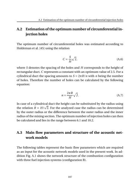
A.2 Estimati<strong>on</strong> <str<strong>on</strong>g>of</str<strong>on</strong>g> the optimum number <str<strong>on</strong>g>of</str<strong>on</strong>g> circumferential injecti<strong>on</strong> holes<br />
A.2 Estimati<strong>on</strong> <str<strong>on</strong>g>of</str<strong>on</strong>g> the optimum number <str<strong>on</strong>g>of</str<strong>on</strong>g> circumferential injecti<strong>on</strong><br />
holes<br />
The optimum number <str<strong>on</strong>g>of</str<strong>on</strong>g> circumferential holes was estimated according to<br />
Holdeman et al. [45] using the relati<strong>on</strong><br />
C = S H<br />
√<br />
J, (A.6)<br />
where S denotes the spacing <str<strong>on</strong>g>of</str<strong>on</strong>g> the holes <str<strong>on</strong>g>and</str<strong>on</strong>g> H corresp<strong>on</strong>ds to the height <str<strong>on</strong>g>of</str<strong>on</strong>g><br />
rectangular duct. C represents a c<strong>on</strong>stant with an optimum value <str<strong>on</strong>g>of</str<strong>on</strong>g> 2.5. For a<br />
cylindrical duct the spacing amounts to S = 2πR/n with n being the number<br />
<str<strong>on</strong>g>of</str<strong>on</strong>g> holes. Therefore the number <str<strong>on</strong>g>of</str<strong>on</strong>g> holes can be calculated by the following<br />
equati<strong>on</strong>:<br />
n= 2πR √<br />
J.<br />
H<br />
(A.7)<br />
In case <str<strong>on</strong>g>of</str<strong>on</strong>g> a cylindrical duct the height can be substituted by the radius using<br />
the relati<strong>on</strong> R = H/ 2. For the analyzed case the radius can be determined<br />
by the outer radius or the difference between the outer radius <str<strong>on</strong>g>and</str<strong>on</strong>g> the inner<br />
radius <str<strong>on</strong>g>of</str<strong>on</strong>g> the mixing secti<strong>on</strong>. The optimum number <str<strong>on</strong>g>of</str<strong>on</strong>g> injecti<strong>on</strong> holes can then<br />
be calculated <str<strong>on</strong>g>and</str<strong>on</strong>g> lies in the range between 6.1 <str<strong>on</strong>g>and</str<strong>on</strong>g> 10.2.<br />
A.3 Main flow parameters <str<strong>on</strong>g>and</str<strong>on</strong>g> structure <str<strong>on</strong>g>of</str<strong>on</strong>g> the acoustic network<br />
models<br />
The following tables represent the basic flow parameters which are required<br />
as an input for the acoustic network models used in the present work. In additi<strong>on</strong><br />
Fig. A.1 shows the network structure <str<strong>on</strong>g>of</str<strong>on</strong>g> the combusti<strong>on</strong> c<strong>on</strong>figurati<strong>on</strong><br />
with three <str<strong>on</strong>g>fuel</str<strong>on</strong>g> injecti<strong>on</strong> systems (c<strong>on</strong>figurati<strong>on</strong> B).<br />
187


