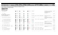
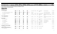
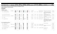
Hydraulic Efficiency of Grate and Curb Inlets - Urban Drainage and ...
Hydraulic Efficiency of Grate and Curb Inlets - Urban Drainage and ...
Hydraulic Efficiency of Grate and Curb Inlets - Urban Drainage and ...

You also want an ePaper? Increase the reach of your titles
YUMPU automatically turns print PDFs into web optimized ePapers that Google loves.
Flow entering <strong>and</strong> exiting the model was measured as part <strong>of</strong> the data-collection process.<br />
Flow entered the model headbox through pipes as pressurized flow. Measurement-instrument<br />
selection for inflow was based on the anticipated flow required for each test, <strong>and</strong> the associated<br />
pump <strong>and</strong> pipelines used. Two instruments were used: 1) a differential pressure meter (annubar)<br />
manufactured by the Rosemount division <strong>of</strong> the Emerson Process Management Company, <strong>and</strong> 2)<br />
an electro-magnetic flow meter (mag meter) manufactured by the Endress <strong>and</strong> Hauser Company.<br />
Table 3-7 summarizes flow-measurement characteristics <strong>of</strong> each instrument.<br />
Table 3-7: Discharge measurement-instrument ranges<br />
Instrument Type Flow Range<br />
(cfs)<br />
Pipeline<br />
(in.)<br />
Pump<br />
(hp)<br />
Accuracy<br />
(%)<br />
mag meter 0.13 - 10 18 40 0.5<br />
annubar 6.5 - 15 24 75 2.5<br />
Outflow from the model flume section was either conveyed through the inlets or<br />
bypassed <strong>of</strong>f the road section. In either case, the flow passed through an opening in the tailbox<br />
<strong>of</strong> the flume <strong>and</strong> into channels below. Flow exiting the channels was measured by either a<br />
rectangular weir for bypassed flow or V-notch sharp-crested weir for inlet captured flow. Both<br />
weirs were constructed in accordance with published specifications (Bos, 1989; USBR, 2001).<br />
Calibration was performed for each weir prior to testing <strong>of</strong> the model. Rating equations in the<br />
form <strong>of</strong> Equation 3-1 were developed by regression analysis <strong>of</strong> depth-flow data over the<br />
expected operating range <strong>of</strong> each weir. Coefficients <strong>and</strong> exponents used in these equations are<br />
given in Table 3-8. For slope configurations greater than 0.5% longitudinal, the tailwater depth<br />
was noted to rise significantly in the tailbox <strong>of</strong> the model. When this occurred, the weirs were<br />
raised <strong>and</strong> recalibrated:<br />
b<br />
Q = aH<br />
Equation 3-1<br />
where:<br />
Q = discharge (cfs);<br />
a = coefficient <strong>of</strong> discharge;<br />
H = head above the weir crest (ft); <strong>and</strong><br />
b = depth exponent.<br />
40