Hydraulic Efficiency of Grate and Curb Inlets - Urban Drainage and ...
Hydraulic Efficiency of Grate and Curb Inlets - Urban Drainage and ...
Hydraulic Efficiency of Grate and Curb Inlets - Urban Drainage and ...

Create successful ePaper yourself
Turn your PDF publications into a flip-book with our unique Google optimized e-Paper software.
On-grade<br />
test data<br />
Directly<br />
calculate<br />
efficiency<br />
as Q captured<br />
divided by<br />
Q Total<br />
Determine<br />
efficiency from<br />
regression<br />
equations for<br />
type 13, 16,<br />
<strong>and</strong> R inlets<br />
Determine<br />
efficiency using<br />
current UDFCD<br />
methods for type<br />
13, 16, <strong>and</strong> R inlets<br />
Determine<br />
efficiency using<br />
improved UDFCD<br />
methods for type<br />
13, 16, <strong>and</strong> R<br />
inlet<br />
Compare<br />
results for<br />
efficiency with<br />
test data <strong>and</strong><br />
recommend<br />
improvements<br />
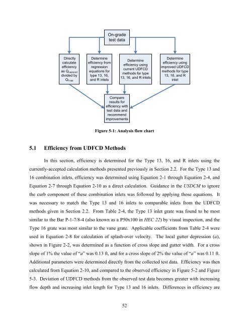
Figure 5-1: Analysis flow chart<br />
5.1 <strong>Efficiency</strong> from UDFCD Methods<br />
In this section, efficiency is determined for the Type 13, 16, <strong>and</strong> R inlets using the<br />
currently-accepted calculation methods presented previously in Section 2.2. For the Type 13 <strong>and</strong><br />
16 combination inlets, efficiency was determined using Equation 2-1 through Equation 2-4, <strong>and</strong><br />
Equation 2-7 through Equation 2-10 as a direct calculation. Guidance in the USDCM to ignore<br />
the curb component <strong>of</strong> these combination inlets was followed by applying those equations. It<br />
was necessary to match the Type 13 <strong>and</strong> 16 inlets to comparable inlets from the UDFCD<br />
methods given in Section 2.2. From Table 2-4, the Type 13 inlet grate was found to be most<br />
similar to the Bar P-1-7/8-4 (also known as a P50x100 in HEC 22) by visual inspection, <strong>and</strong> the<br />
Type 16 grate was most similar to the vane grate. Applicable coefficients from Table 2-4 were<br />
used in Equation 2-8 for calculation <strong>of</strong> splash-over velocity. The local gutter depression (a),<br />
shown in Figure 2-2, was determined as a function <strong>of</strong> cross slope <strong>and</strong> gutter width. For a cross<br />
slope <strong>of</strong> 1% the value <strong>of</strong> “a” was 0.13 ft, <strong>and</strong> for a cross slope <strong>of</strong> 2% the value <strong>of</strong> “a” was 0.11 ft.<br />
Additional parameters were determined directly from the collected test data. <strong>Efficiency</strong> was then<br />
calculated from Equation 2-10, <strong>and</strong> compared to the observed efficiency in Figure 5-2 <strong>and</strong> Figure<br />
5-3. Deviation <strong>of</strong> UDFCD methods from the observed test data becomes greater with increasing<br />
flow depth <strong>and</strong> increasing inlet length for Type 13 <strong>and</strong> 16 inlets. Differences in efficiency are<br />
52