Sea Launch User's Guide
Sea Launch User's Guide
Sea Launch User's Guide
Create successful ePaper yourself
Turn your PDF publications into a flip-book with our unique Google optimized e-Paper software.
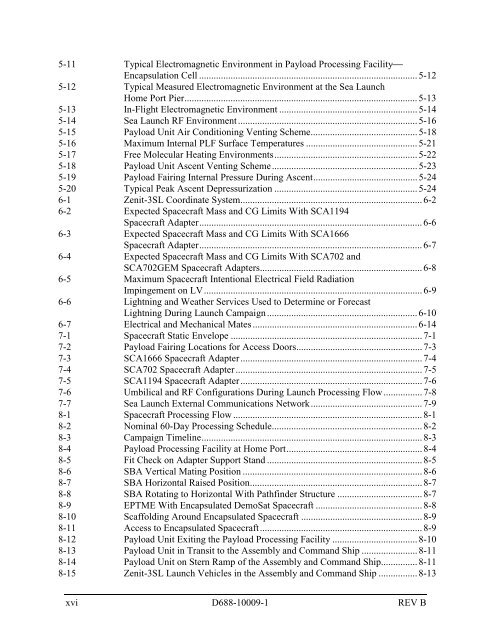
5-11 Typical Electromagnetic Environment in Payload Processing Facility⎯<br />
Encapsulation Cell .......................................................................................... 5-12<br />
5-12 Typical Measured Electromagnetic Environment at the <strong>Sea</strong> <strong>Launch</strong><br />
Home Port Pier................................................................................................ 5-13<br />
5-13 In-Flight Electromagnetic Environment ......................................................... 5-14<br />
5-14 <strong>Sea</strong> <strong>Launch</strong> RF Environment.......................................................................... 5-16<br />
5-15 Payload Unit Air Conditioning Venting Scheme............................................ 5-18<br />
5-16 Maximum Internal PLF Surface Temperatures .............................................. 5-21<br />
5-17 Free Molecular Heating Environments........................................................... 5-22<br />
5-18 Payload Unit Ascent Venting Scheme............................................................ 5-23<br />
5-19 Payload Fairing Internal Pressure During Ascent........................................... 5-24<br />
5-20 Typical Peak Ascent Depressurization ........................................................... 5-24<br />
6-1 Zenit-3SL Coordinate System........................................................................... 6-2<br />
6-2 Expected Spacecraft Mass and CG Limits With SCA1194<br />
Spacecraft Adapter............................................................................................ 6-6<br />
6-3 Expected Spacecraft Mass and CG Limits With SCA1666<br />
Spacecraft Adapter............................................................................................ 6-7<br />
6-4 Expected Spacecraft Mass and CG Limits With SCA702 and<br />
SCA702GEM Spacecraft Adapters................................................................... 6-8<br />
6-5 Maximum Spacecraft Intentional Electrical Field Radiation<br />
Impingement on LV.......................................................................................... 6-9<br />
6-6 Lightning and Weather Services Used to Determine or Forecast<br />
Lightning During <strong>Launch</strong> Campaign.............................................................. 6-10<br />
6-7 Electrical and Mechanical Mates .................................................................... 6-14<br />
7-1 Spacecraft Static Envelope ............................................................................... 7-1<br />
7-2 Payload Fairing Locations for Access Doors.................................................... 7-3<br />
7-3 SCA1666 Spacecraft Adapter........................................................................... 7-4<br />
7-4 SCA702 Spacecraft Adapter............................................................................. 7-5<br />
7-5 SCA1194 Spacecraft Adapter........................................................................... 7-6<br />
7-6 Umbilical and RF Configurations During <strong>Launch</strong> Processing Flow................ 7-8<br />
7-7 <strong>Sea</strong> <strong>Launch</strong> External Communications Network.............................................. 7-9<br />
8-1 Spacecraft Processing Flow .............................................................................. 8-1<br />
8-2 Nominal 60-Day Processing Schedule.............................................................. 8-2<br />
8-3 Campaign Timeline........................................................................................... 8-3<br />
8-4 Payload Processing Facility at Home Port........................................................ 8-4<br />
8-5 Fit Check on Adapter Support Stand ................................................................ 8-5<br />
8-6 SBA Vertical Mating Position .......................................................................... 8-6<br />
8-7 SBA Horizontal Raised Position....................................................................... 8-7<br />
8-8 SBA Rotating to Horizontal With Pathfinder Structure ................................... 8-7<br />
8-9 EPTME With Encapsulated DemoSat Spacecraft ............................................ 8-8<br />
8-10 Scaffolding Around Encapsulated Spacecraft .................................................. 8-9<br />
8-11 Access to Encapsulated Spacecraft................................................................... 8-9<br />
8-12 Payload Unit Exiting the Payload Processing Facility ................................... 8-10<br />
8-13 Payload Unit in Transit to the Assembly and Command Ship ....................... 8-11<br />
8-14 Payload Unit on Stern Ramp of the Assembly and Command Ship............... 8-11<br />
8-15 Zenit-3SL <strong>Launch</strong> Vehicles in the Assembly and Command Ship ................ 8-13<br />
xvi D688-10009-1 REV B


