

2011 EMC Directory & Design Guide - Interference Technology
2011 EMC Directory & Design Guide - Interference Technology
2011 EMC Directory & Design Guide - Interference Technology

Create successful ePaper yourself
Turn your PDF publications into a flip-book with our unique Google optimized e-Paper software.
filters<br />
A c c ur at e F e e d t hr o u g h C a pa c i t o r Me a s ur e m e n t s at Hi g h Frequencies<br />
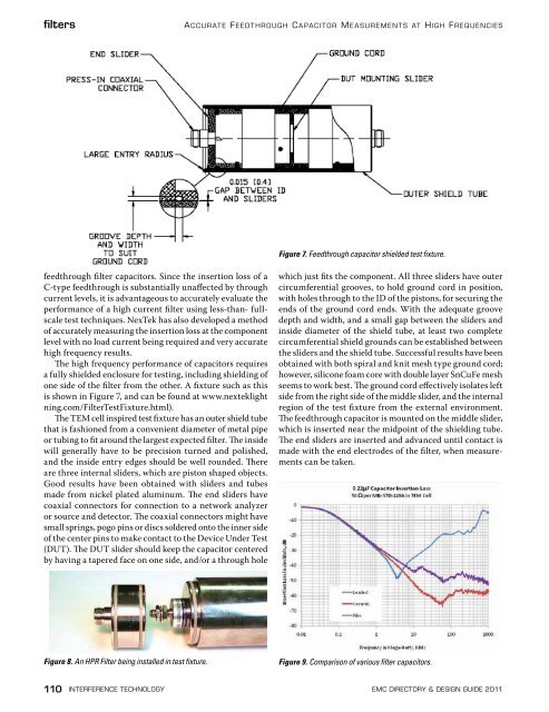
Figure 7. Feedthrough capacitor shielded test fixture.<br />
feedthrough filter capacitors. Since the insertion loss of a<br />
C-type feedthrough is substantially unaffected by through<br />
current levels, it is advantageous to accurately evaluate the<br />
performance of a high current filter using less-than- fullscale<br />
test techniques. NexTek has also developed a method<br />
of accurately measuring the insertion loss at the component<br />
level with no load current being required and very accurate<br />
high frequency results.<br />
The high frequency performance of capacitors requires<br />
a fully shielded enclosure for testing, including shielding of<br />
one side of the filter from the other. A fixture such as this<br />
is shown in Figure 7, and can be found at www.nexteklight<br />
ning.com/FilterTestFixture.html).<br />
The TEM cell inspired test fixture has an outer shield tube<br />
that is fashioned from a convenient diameter of metal pipe<br />
or tubing to fit around the largest expected filter. The inside<br />
will generally have to be precision turned and polished,<br />
and the inside entry edges should be well rounded. There<br />
are three internal sliders, which are piston shaped objects.<br />
Good results have been obtained with sliders and tubes<br />
made from nickel plated aluminum. The end sliders have<br />
coaxial connectors for connection to a network analyzer<br />
or source and detector. The coaxial connectors might have<br />
small springs, pogo pins or discs soldered onto the inner side<br />
of the center pins to make contact to the Device Under Test<br />
(DUT). The DUT slider should keep the capacitor centered<br />
by having a tapered face on one side, and/or a through hole<br />
which just fits the component. All three sliders have outer<br />
circumferential grooves, to hold ground cord in position,<br />
with holes through to the ID of the pistons, for securing the<br />
ends of the ground cord ends. With the adequate groove<br />
depth and width, and a small gap between the sliders and<br />
inside diameter of the shield tube, at least two complete<br />
circumferential shield grounds can be established between<br />
the sliders and the shield tube. Successful results have been<br />
obtained with both spiral and knit mesh type ground cord;<br />
however, silicone foam core with double layer SnCuFe mesh<br />
seems to work best. The ground cord effectively isolates left<br />
side from the right side of the middle slider, and the internal<br />
region of the test fixture from the external environment.<br />
The feedthrough capacitor is mounted on the middle slider,<br />
which is inserted near the midpoint of the shielding tube.<br />
The end sliders are inserted and advanced until contact is<br />
made with the end electrodes of the filter, when measurements<br />
can be taken.<br />
Figure 8. An HPR Filter being installed in test fixture.<br />
Figure 9. Comparison of various filter capacitors.<br />
110 interference technology emc <strong>Directory</strong> & design guide <strong>2011</strong>


![[ thursday ] morning sessions 8:30 am-noon - Interference Technology](https://img.yumpu.com/23176841/1/190x247/-thursday-morning-sessions-830-am-noon-interference-technology.jpg?quality=85)

